(Not Another) Propolis Volume Pot Thread

Ginsly

Well-known member
I swear, I tried to bump existing threads. :)

This kind of takes away the charm/simplicity of a pot-less pedal, but I'd love a Vol cut. I assume the Propolis is a bit over unity as-is...?

What's the best way to do this without affecting the stock Max Volume of the Propolis? That seemed to be a possible issue in another thread.

This is part of my "pedal education", so I reeeeally need this spelled out so I understand where to connect what, and if that's the ONLY thing connected to that spot. This is what one Vol Modder said:

"You just got to hook one lug on the "out" pad of the PCB, one lug to ground and one lug to the out jack."

1) So - there will be TWO wires going to the "Out" pad at the bottom of the PCB? One from the pot (lug #3?) and one from the footswitch?

2) A different lug (#1?) to ground - I see this mentioned often. Where do I physically connect to Ground? At the Power Jack or at the bottom of the PCB where the footswitch connects to Ground?

3) The last lug (#2?) to the Out Jack - Tip I assume? This is in addition to the wire already connecting the Out Jack & Footswitch?

Yes, I'm this much of a dum-dum still. I really only started understanding ANY of this about a month ago. Situations like these help me understand WHY things are the way they are, and lead to understanding a whole host of other things. Thanks for your patience, this forum has been incredibly helpful and fun so far.
 
Is your goal to have a pot with an in/out footswitch and no other controls? So the top of the enclosure would have the footswitch and LED on it but no other hardware? Isn't that what the build document already does? What do you want that is different? An internal way to reduce the output level? It looks like you have not yet built this to find out whether the output is higher than you want it to be.

On the build doc it looks like you could replace the 330K R17 with a trim pot (maybe a 500K) and adjust it to set your desired output level. You could even use this to simplify replacing R17: https://www.pedalpcb.com/product/trimmit/
 
Last edited:
@zgrav I’m trying to incorporate an external A100K Volume pot (not a trim) so I can reduce the overall volume if need be. Sometimes I stack pedals and try different Vol levels, so an external pot is helpful.
 
Got it. So you want the option of being able to go louder or softer than unity depending on the setting for the external volume pot. Are you using the PPCB board? If so you will need to consider how the pot placement will affect the circuit board (and LED) placement. I suggest looking at the way volume pots are mounted for Veroboard layouts so you can use the "out" from the PCB to go to the volume pot, then have one lug of the volume pot go to the footswitch and the remaining lug on the volume pot go to ground. You may also want to raise the value of R17 on the PPCB circuit board to increase the output level going to the volume pot.

Here is a link to the Veroboard layout for this circuit. If you read through the comments there are discussions about modding it for a volume pot and a sag pot. https://tagboardeffects.blogspot.com/2020/07/third-man-records-bumble-buzz.html#comment-form
 
Yep I'm using the Propolis board. I just want to be able to cut volume down on the fly if I have to, as I don't think I can boost the available volume on the Propolis without installing a little LPB circuit or something... I'm certainly not ready for that, as simple as it may be. Sounds like I may be able to give it a little more available volume via bumping up R17 though - thanks for that tip. Not sure how high to go, though.

I'll check out that Veroboard layout. Still confused about the wiring.
so you can use the "out" from the PCB to go to the volume pot
"Out" from the PCB - meaning at the bottom where the footswitch also connects to the board? I would connect both the footswitch and a pot lug here? Pic:
Screen Shot 2023-12-28 at 12.12.44 PM.png
then have one lug of the volume pot go to the footswitch
Not sure where to connect it to the footswitch (I'm using a footswitch pcb). Like I said, I REALLY need this spelled out! Still very green :)
and the remaining lug on the volume pot go to ground
Again, I'm not sure where to physically connect the lug to Ground via hookup wire.
 
you will not have one wire directly connect the "out" on the circuit board to the footswitch. you are putting the volume pot in between the "out" and the footswitch, meaning the "out" wire from the PCB goes to the volume pot and a wire from the volume pot goes to the footswitch where the wire from the "out" would have gone. you can connect the remaining unused "lug" on the volume pot to a ground connection -- probably easiest to solder it to one of the ground lugs on the in or our audio jacks. spend more time looking at the wiring for the Vero board and understanding the comments that are posted on it about adding a volume pot to the off-board wiring.

there is also a link on that website that has more general information about the off-circuit-board wiring for Vero projects: https://tagboardeffects.blogspot.com/2012/02/offboard-wiring.html
Ok, this is making a lot more sense now. Thanks for the explanation! Will investigate further, but your input has been very helpful. Much appreciated.
 
Propolis' OUT > Lug 3 of the volume pot
VOL Lug 1 to ground.
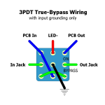
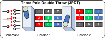
VOL Lug 2 > Footswitch daughterboard's "BOARD OUT" or 3PDT lug 7 if wiring it direct ("PCB OUT" in diagram below):

3PDTWiring-2.png
 
Propolis' OUT > Lug 3 of the volume pot
VOL Lug 1 to ground.
VOL Lug 2 > Footswitch daughterboard's "BOARD OUT" or 3PDT lug 7 if wiring it direct ("PCB OUT" in diagram below):

View attachment 64390
Excellent!! Thank you, there it is! Where would you suggest I connect Lug 1 to Ground? I see that said a lot, and I’m never sure where best to do it. I assume it’s situational and ANY ground point will do- on the in/out jacks, power jack, or on the PCB (although that sounds a bit crowded).
 
Excellent!! Thank you, there it is! Where would you suggest I connect Lug 1 to Ground? I see that said a lot, and I’m never sure where best to do it. I assume it’s situational and ANY ground point will do- on the in/out jacks, power jack, or on the PCB (although that sounds a bit crowded).

Whatever's most convenient, unless it's on a pedal that has an LFO, keep the audio path away from that LFO.
Oh, right, this is like the Union Tube & Transistor Bumble Buzz. No LFO. No pots. Yeah, I guess the power jack or the gnd at the top of the board would do.


Maybe we should add an optional volume pot to the layout?

What would be the Propoilis of that?

Serves no Propolis...


Wait a sec... I know... it... it's... it's my... MY SPECIAL PROPOLIS!


HEY EveryBody! I just FoUnD my SpEcIAL pRoPoLiS!

JERK+4.JPG
 
Yeah, I guess the power jack or the gnd at the top of the board would do.
Gotcha! Zgrav had mentioned replacing R17 with a higher value (?) to send more signal to the Volume pot... I always figured you couldn't really raise the maximum volume of a circuit (PCB at least) without adding a little LPB etc to it, which I'm not quite ready for. It would be nice to send as much level as possible to the Vol pot, considering I can simply turn it down if need be. Waddya think? Possible?
 
Gotcha! Zgrav had mentioned replacing R17 with a higher value (?) to send more signal to the Volume pot... I always figured you couldn't really raise the maximum volume of a circuit (PCB at least) without adding a little LPB etc to it, which I'm not quite ready for. It would be nice to send as much level as possible to the Vol pot, considering I can simply turn it down if need be. Waddya think? Possible?
Zgrav is far more knowledgeable than me.
I think Zgrav is correct, makes sense: By raising R17, less signal gets dumped to ground so more is forced through the volume pot.


I always figured you couldn't really raise the maximum volume of a circuit (PCB at least) without adding a little LPB etc to it

Well, a TUBE-SCREAMER doesn't have an LPB, so where/how are the modders getting extra gain out of the stock TS-808 ?
They're manipulating the existing circuitry, increasing the resistor-value on the op-amp's feedback loop and/or installing a larger GAIN pot value, bumping it from 500k up to 1M...
Back to the task at hand, VOL on a Mumblegrumblebumble preposterous Propolis:


Here's something else to try: socket R17, don't populate it, add your VOL pot and see how that goes. Without R17, ALL your signal goes to the VOL pot. NOTA BENE! This has a knock on effect, it may affect your output impedance and overall tone, since R17 interacts with C9 and the rest of the tone-stack. How much? Is it relevant? I don't know.

Here's another idea to try...
Connect VOL Leg3 to circuit-side-R17
Connect VOL Leg1 to GND-side-R17
Connect VOL Leg2 to your 3PDT
OUT on the PCB connects to... nada, nothing, zip, zero, no love for that pad...


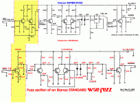
You can compare the Propolis schematic to schematics from an Univox Super Fuzz or Ibanez Standard Fuzz, that'll give you an idea of where the Propolis originated and how pots were used prior to them being stripped from the circuit.

The original USP as well as the Kay F-1 had 100k to ground, BUT that's after the tone-stack's recovery boost section. The Ibby Standard Fuzz had a paltry 10k.

If you're not into breadboarding, then socket R17, try different values until you get what you want with the VOL-pot's output across its sweep. Once you find the sweet-spot R17 value, solder in one side if you're worried about it falling out of the socket.


That gives me another idea: you could use one of the Muffin Crumbs for a gain recovery stage and wire up the volume to that.


Univox superfuzz vs Ibby standard fuzz_diffs.gif
 
Here's another idea to try...
Connect VOL Leg3 to circuit-side-R17
Connect VOL Leg1 to GND-side-R17
Connect VOL Leg2 to your 3PDT
Huh! This seems interesting, but so does socketing R17 and trying some different things... Thanks for the explanation, and yes, @zgrav was very, very helpful in getting this ball rollin'!

For the above situation, where would I connect VOL Leg 2 on the 3PDT's board? I assume the "Out" space, since there is nothing coming from "Out" on the main PCB anymore?

Also, a more general question about sockets. Some people seem to HATE them, I'm assuming because of reliability issues (i.e. components falling out). I'm not terribly concerned about that for now, and thought... on one of the simpler boards I have (like the Executive (Bosstone) Fuzz) - why not socket ALL components for now? It won't be seeing the road, and I can try some different things all over the place while I'm learning all of this. I actually have what is likely an early Monsterpiece AD2000 (Bosstone) where Richard did just that. Still sounds great 15 years later!

Aside from components falling out, does this increase noise or anything? I've read that over time the contact points between the socket and component leg can get dirty or corroded, but again, I haven't noticed anything like that with the weird AD2000 I have.

Yes, correct, Connect VOL 2 to 3PDT as indicated in post #8.

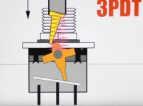
Here's some 3PDT info to help you better understand what the stompers are doing:

3PDT-inside.jpg


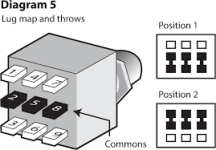
1703891298293.png 1703891409295.png

And of course, there are many ways to wire a 3PDT to make it do what you want; I prefer wiring them as per my previous post's 3PDT-diagram.
Compare the above diagrams to the way the stomper is wired in post#8 and you'll begin to fathom what's doing what and why.


SOCKETS:
When I was too lazy to breadboard, I completely (COMPLETELY) socketed a couple Muff boards to build circuits and compare them. I've socketed a LOT of other PCBs when playing around with EQ curves and diodes and ... I've never had a problem with any sockets EXCEPT for the crap (IMO) so-called fly-leaf IC-sockets. Get Machined IC sockets.

I've never toured to any extent, but if I did, then I might worry about sockets losing components. You'd have to swap a lot of parts in/out to wear-out a socket — what is a breadboard? Nothing but a buncha sockets some of which are connected, and they DO wear out. The only way sockets can cause noise is if the component is loose and the contact isn 't good and you're playing at volumes that are rattling dishes off the shelves and so in turn rattling components within their sockets. I've rattled things off the shelf, never had a problem with sockets once I got better resistors that don't have leads the thickness of a strand of hair.

Yes, some people here despise sockets with a vengeance, or they hate a particular PCB supplier, or refuse to use stranded-wire, or have a particular way of wiring a 3PDT...
Try sockets. Decide for yourself whether you like them or not. You'll figure out which 3PDT wiring scheme makes the most sense to you, and all the other minutiae-preferences that we develop.

I socket less now, breadboard more.
 
@Feral Feline Un. Freakin. REAL! Very, very helpful response. I learn in a very strange way, and I'm trying to play catch-up VERY quickly. That being said, I'm not afraid to ask some very, very "dumb" questions. Luckily, you and many others here (including PedalPCBers like @Robert) have been patient, thorough, and kind.

I'm not sure if there's an "introduce yourself" section here, but I've been around the block as a musician but this stuff is all new to me. For one, I played with Dean Ween for a few years during Ween's hiatus and I still have some swag I made for the shows (I'm a printmaker). Hopefully I can show my appreciation at some point and send out some stuff. Seriously! This has been very illuminating and very fun. And I'm just startin out. :)
 
Back
Top