SOLVED Protein in 1590BB leds flashed and now don’t work

ADAOCE

Well-known member
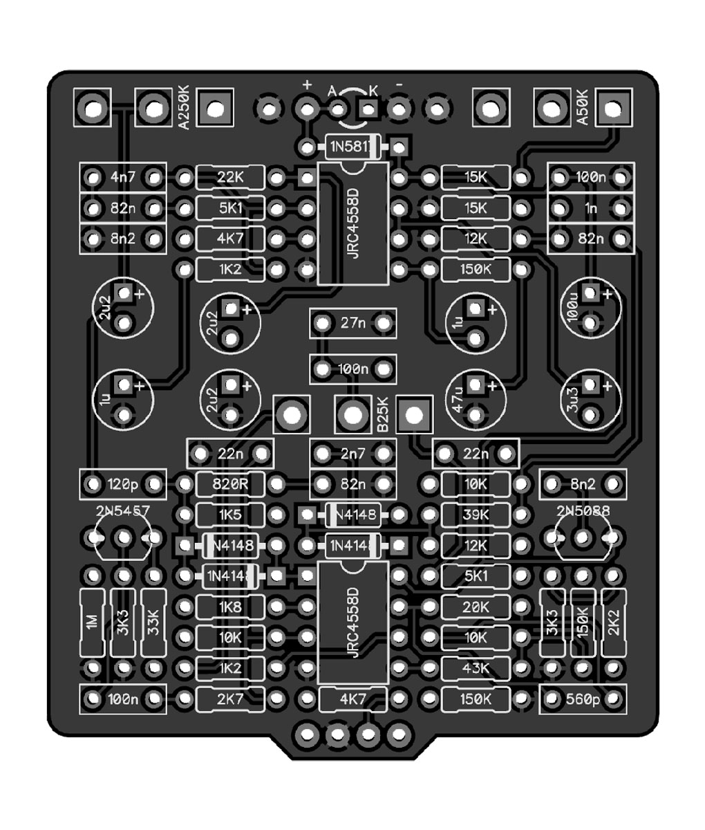
Hey guys so I’ve been painstakingly fitting this pedal in the enclosure and I finally finished all the wiring and in my haste to test it out I forgot to put in all the ICs and the two transistors. When I powered it up the leds blinked and I heard a little pop. The leds now don’t turn on.

I decided to put the ICs and transistors in and then try it again and the blue side only passes sound in bypass and the green side passes sound in both but the circuit doesn’t have nearly enough gain.

tonight I plan to get the multi meter out and check voltages and stuff. I’m just curious what’s would have caused the leds to pop and flash like that. As you can see in the picture I bypassed the sw pad on the pcb and wired directly to the led. Did I bypass the CLR?

thanks guys
 

Attachments

  • E83B023F-32BB-4F43-8FE3-0E1C0D495682.jpeg
    E83B023F-32BB-4F43-8FE3-0E1C0D495682.jpeg
    531.4 KB · Views: 34
I’ll also add that I’m definitely going to use the adapter for the 1590BB because I had to squish the boards down to close the lid and it was a little tight. I insulated the underside of the lid with some duct tape but I’m wondering if pushing the boards down shorted something out. I can take everything out of the enclosure tonight too and get more pictures.
 
Hmm after looking at the wiki for 2 in 1 wiring it looks like I didn’t do the power wiring correctly. On the board on the right it says I should have wired the power ground to the left ground pad for the input Jack instead of the negative pad. I also didn’t connect my output Jack ground to the either board I just jumped from the input Jack ground to the output Jack ground.

would this bungle cause some issues?
 
By not connecting to SW you have bypassed CLR which is why both Led's have blown.
If you have not grounded at least one of the top negative (Ground) pads of each PCB, it will not work!
If you have not put Dust covers on all the pots, It will short out for sure.
 
By not connecting to SW you have bypassed CLR which is why both Led's have blown.
If you have not grounded at least one of the top negative (Ground) pads of each PCB, it will not work!
If you have not put Dust covers on all the pots, It will short out for sure.
Thanks for confirming the CLR. I’ll get new leds and use the SW pads. Would this have affected any other part of the circuit?

I wired both negative leads from the DC Jack to the negative pads on each pcb.

I put dust covers on the bare pots underneath.

tonight I’ll take it apart and inspect underneath the board and see if any of my wires look troubling. I’m a little bummed these two boards have some of what I think are my best looking solder joints and wiring everything up went pretty smoothly as well.
You just need to put 4k7 resistors on your power leads to the anodes of your Led' because you have bypassed the Cathode's on the PCB's which go to the CLR's & SW's.
 
Got some voltages
Blue side

IC1
1: 3.87
2: 0
3: 0
4: 0
5: 0
6: 0
7: 8.63
8: 7.43

IC2
1: 4.3
2: 4.3
3: 0
4: 0
5: .06
6: .27
7: 4.3
8: 8.63

green side
IC1
1: 4.3
2: .09
3: .24
4: 0
5: 0
6: 4.3
7: 4.3
8: 8.63

IC2
1: 4.3
2: 4.3
3: .06
4: 0
5: .07
6: .16
7: 4.3
8: 8.63
 
This is not going to have a lot of gain with 100k Gain pots!
The voltages on IC1 Blue are not right!!!
Here is a Resistor Calculator to check values.
Click on Bands for 5 Bands :
 
This is not going to have a lot of gain with 100k Gain pots!
The voltages on IC1 Blue are not right!!!
Here is a Resistor Calculator to check values.
Click on Bands for 5 Bands :
Ok good to know. I’ll double check all my resistor values
 
Hmmmm I had IC1 and IC2 labeled backwards so upon further review it is actually IC2 that you see with the bad voltages anddd I just realized I put a TL072 not a TL071. I’ll swap these out and see what happens.
Resistors are all correct after checking again
 
Ok so the blue side works once I put the TL071 in there and HOLY SMOKES that side alone is worth everything just wow.

Ill post the build report when I get the replacement leds. Green side is ok idk if there is something not quite right in the gain section or I just don’t have the right expectations. Either way it’s still fine as it is I probably just need to dial that in a bit.
Thanks for the assist
Green side is based on Nobels ODR-1, that has a 250K Drive pot, I read that he had tamed the Gain on this & 100K would do it!
 
Back
Top