Pythagoras V2 to V3 conversions? (Radium Springs)

TheToneGeek

New member
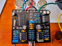
Hello! I finally got around to building the Pythagoras V2 Radium Springs and I have the same hiss and weird (low) mix volume past 2 o'clock issues as other members mentioned. Does anyone have the original Pythagoras v2 documentation and/or what changed between the circuit board I have and the V3 to improve the hiss and mix? Or did anything change between the silkscreen and the documentation?

I populated the v2 board by using the silkscreen values as a guide so I suspect that the silkscreen does not match up to updated schematics. I compared the v2 schematic to v3 and couldn't tell any difference so I'm thinking it's changed values between the silkscreen and the documentation. The only thing I printed out was the schematic and not the rest of the v2 documentation :-(

Thank you in advance. -Ryan
 
Thank you for the quick reply. I printed out the V2 documentation at the time of purchase of the board (Feb 19, 2019). The board looks different from your current Radium Springs 3D pic layout and does not match 100% the v3 documentation on page 1. It looks like there are 6 resistors on the top right corner (R7/R8/R5/R16/R3/R18) in the v3 documentation vs the 5 that is on my physical board? Is it possible to tell if the silkscreen was altered between boards selling on Feb 19th, 2019 and now? I'm going to give my build a solid look over too meanwhile for human error, but it's odd I am having the same behavior as others where the full wet mix is very low volume and the high level of signal to hiss ratio which is why I think something on the silkscreen (now covered with components) might have been a different value than intended. Thank you in advance for your insight.

IMG_20200320_092234.jpg
 
Last edited:
Here is the board I received/used. Note: The orange drop is .0022uF per the doc/silkscreen, I just ran out of the nice MLCCs.

Screen Shot 2020-03-21 at 9.29.13 AM.jpg
 
Last edited:
Ok. I think I found a difference between v2 and v3. The v3 has a 100k impedance resistor (R20 on v3 schematic) and my v2 does not have that. I'll solder that direct to my output jack and see if that helps anything.

UPDATE: I did add the 100k at the jack itself with no audible difference to my ears.

quick unlisted YouTube video of the pedal with the wet hiss and mix volume drop.
 
Last edited:
You ever get this working? The FV-1 is a very quiet chip, so there has to be something wrong on the board. What's all that funk on the FV-1? Your board looks like it has flux residue everywhere. Contamination around pins 9 & 10 of the FV-1, C7 and the XTAL will mess up the clock and that can cause noise and other performance problems. Clean the board thoroughly with IPA, don't let dirty IPA get into the pots. Have you verified that all of the yellow caps are the correct values?
 
You ever get this working? The FV-1 is a very quiet chip, so there has to be something wrong on the board. What's all that funk on the FV-1? Your board looks like it has flux residue everywhere. Contamination around pins 9 & 10 of the FV-1, C7 and the XTAL will mess up the clock and that can cause noise and other performance problems. Clean the board thoroughly with IPA, don't let dirty IPA get into the pots. Have you verified that all of the yellow caps are the correct values?
I just finished my Radium Springs. I have the same problem as another user. Very low output when the effect is on. Works ok, just low output. Comparing my board to theirs, I noticed my board states B10K and the docs state B100k on the mix. I tried both. Did not really notice a heap of differece. My Board is a V3. I don't know which is right, but the resistors at R12, mine states 100 ohm. the other image appears to be 15k, no idea which it should be?? My R11 is 22K the other is 100 ohm, and the others in that row are different to mine as well? (See Image) BUT theirs is low volume as well???? I confused. I have low volume and have no idea how to increase it! I have checked all my values, re-soldered all my joints, everything appears well and it works right, just about half the volume when the effect is on.
 

Attachments

  • 20230212_113626.jpg
    20230212_113626.jpg
    1.3 MB · Views: 5
Last edited:
I just finished my Radium Springs. I have the same problem as another user. Very low output when the effect is on. Works ok, just low output. Comparing my board to theirs, I noticed my board states B10K and the docs state B100k on the mix. I tried both. Did not really notice a heap of differece. My Board is a V3. I don't know which is right, but the resistors at R12, mine states 100 ohm. the other image appears to be 15k, no idea which it should be?? My R11 is 22K the other is 100 ohm, and the others in that row are different to mine as well? (See Image) BUT theirs is low volume as well???? I confused. I have low volume and have no idea how to increase it! I have checked all my values, re-soldered all my joints, everything appears well and it works right, just about half the volume when the effect is on.
It is always best to follow the silkscreen values on whatever version of the PCB you have. Even when the BOM and/or schematic says something different, follow the values printed in the silkscreen on the PCB. Comparing one version to another will oftentimes find variations because changes were made the latest version.
 
Hi, I have the V2 PCB (same as in the picture above from the Tone Geek). The one with some moved around Resistors and the missing R20 (100K). So should I go with the values printed on the PCB? Should I add the missing 100K Resistor elsewhere or not worry about it? Thanks!
 
Hi, I have the V2 PCB (same as in the picture above from the Tone Geek). The one with some moved around Resistors and the missing R20 (100K). So should I go with the values printed on the PCB? Should I add the missing 100K Resistor elsewhere or not worry about it? Thanks!
Yes, stick with the component values printed on the PCB. On the Pythagoras V2 PCB, R20 simply does NOT exist. However, it can can easily be added by simply connecting a 100K resistor between ground and the output side of C6. It should make no audible difference; merely establishing an output impedance of about 100K.
 
Yes, stick with the component values printed on the PCB. On the Pythagoras V2 PCB, R20 simply does NOT exist. However, it can can easily be added by simply connecting a 100K resistor between ground and the output side of C6. It should make no audible difference; merely establishing an output impedance of about 100K.
👍
 
Back
Top