RAT vs RAT2

tktk

New member
Hi, I'm a RAT fanboy and need some experts' help.
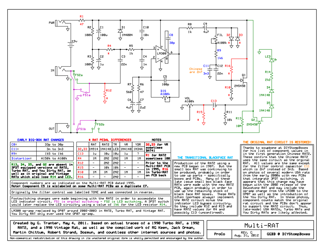
Could anyone tell me what are the C13 and R15 for?
I'm trying to figure out why the RATs sound different from the RAT2s. All my RATs sound clearer and have more clarity.

BTW, I have about 5 early 90s RAT2s right now, all of which have a 22M register (red-red-blue-gold) for R13, not 10M. I also have a RAT which has the RAT2 board, and it has a 2.2M (red-red-green-gold) for the same spot. I believe it's just for the LED circuit, so not a big deal perhaps?

Thanks in advance. multi-rat-clear.png
 
Last edited:
Hi, I'm a RAT fanboy and need some experts' help.

Could anyone tell me what are the C13 and R15 for?
I'm trying to figure out why the RATs sound different from the RAT2s. All my RATs sound clearer and have more clarity.

BTW, I have about 5 early 90s RAT2s right now, all of which have a 22M register (red-red-blue-gold) for R13, not 10M. I also have a RAT which has the RAT2 board, and it has a 2.2M (red-red-green-gold) for the same spot. I believe it's just for the LED circuit, so not a big deal perhaps?

Thanks in advance.
I can't zoom in on that picture on my phone well, but it's connected to the dpdt foot switch. So, important to the switching circuit but not to the overall RAT sound.
 
I can't zoom in on that picture on my phone well, but it's connected to the dpdt foot switch. So, important to the switching circuit but not to the overall RAT sound.
I also attached the pic so that maybe you can see it better.

Do you mean the R13?
C13 and R15 are in between the volume pot and the JFET amp circuit.
The RAT has C13 (1u) but R15 is absence, and the RAT2 has C13 (10u) and R15 (10k).
 
C13 is a DC blocking cap to block DC from the output. It also forms a R filter(single pole high pass filter) with R15
You can work out the corner frequenciws with an online calculator
R15 parallels with R11 to limit maximum output and set the output impedance of the circuit.
Thanks for the explanations. So, there's little to no chance those two components could affect the tone?
 
Thanks for the explanations. So, there's little to no chance those two components could affect the tone?
I didn't read the schematic right -- sorry. Couldn't zoom, so I missed the volume pot (needed more coffee!).

To answer, c13 will change the tone some..it will allow more/less bass. The c13/R15 is a filter (explained aboved). JWin explains it pretty well, and gives a great link to the frequency rolloff calculator
 
If you omit r15 use 1uf or 10uf, it really doesn't matter in that case. If you include r15 definitely use the 10uf output cap. Like jwin said the resistor is in parallel with the volume pot and interact together changing the filter created with the output cap.

Personally on the rats I've built I used 1uf output cap, no R15, and a linear volume pot instead of logarithmic pot. It doesn't feel like I have to crank the volume pot as much. I also think a linear tone pot has a better sweep so I only use a logarthmic pot for the distortion control.
 
c13 will change the tone some..it will allow more/less bass.
Not really, at 1uF and hooked up to a 10K resistor, the corner frequency is 15Hz, so well below the range of human hearing.

For DC blocking, you usually pick such large values (1uF or larger) specifically so that their effect is outside the range of human hearing. You usually see 10uF electrolytics in older pedals (like the Rat, and lots of old Boss designs) because even though 10uF is overkill for audio purposes (1.5Hz is even further below the range of human hearing), it's what they had on hand (and 1uF film caps were huge and expensive - still are, comparatively).

(and conversely, you see 1uF film in lots of newer designs because it's large enough to pass all audio frequencies, film caps are smaller and cheaper than they used to be to make using them in pedals more feasible, and film should both sound "better" and won't leak dc)
Makes sense. I figured that had a little bit more impact on it to shape the output. I'm not that circuit smart. :)
 
Makes sense. I figured that had a little bit more impact on it to shape the output. I'm not that circuit smart. :)
yeah like whenever I see a cap of like 220n or less in the audio path I think "tone shaping" but as soon as it hits 1uF I think "blocker".

(and then you have the Timmy in the middle, with an 820nF that *just* barely hits the audible range at some settings lol)
 
R12 sets the input Impedance for the Rat2 at 2M2. It was omitted on the Rat so not sure what the impedance is for it. That may account for some of the difference.
 
C13 is a DC blocking cap to block DC from the output. It also forms a R filter(single pole high pass filter) with R15
You can work out the corner frequenciws with an online calculator
R15 parallels with R11 to limit maximum output and set the output impedance of the circuit.
So the term corner frequencies, or corner frequenciws, if you will, refers to the high and low cutoffs for what a circuit allows through?
 
I'm trying to figure out why the RATs sound different from the RAT2s. All my RATs sound clearer and have more clarity.
In what kind of way? Also what kind of Rats and Rat2s are we talking about?
Clearer in what way? Does adjusting gain and filter mostly get you in the same ballpark? Using your ears, not eyes that is.
In general Rats with the OP07 sound a bit more clearer, but they also have a midrange thing that you might perceive as less clear.
LM308 Rats on the other hand are actually fuzzier and saggier with the gain high.

BTW, I have about 5 early 90s RAT2s right now, all of which have a 22M register (red-red-blue-gold) for R13, not 10M. I also have a RAT which has the RAT2 board, and it has a 2.2M (red-red-green-gold) for the same spot. I believe it's just for the LED circuit, so not a big deal perhaps?
That's all just the LED circuitry.

R15 is absence, and the RAT2 has C13 (10u) and R15 (10k)
R15 is a pulldown resistor that is not necessary, as the volume pot acts as pulldown anyway. But having it there has approximately the same effect as using a 10K instead of 100K pot.

R12 sets the input Impedance for the Rat2 at 2M2. It was omitted on the Rat so not sure what the impedance is for it. That may account for some of the difference.
It's just a pulldown resistor so the circuit doesn't pop when engaged. It has some influence on the input impedance, but that is mostly set by the op amp itself and R4.
 
yeah like whenever I see a cap of like 220n or less in the audio path I think "tone shaping" but as soon as it hits 1uF I think "blocker".

(and then you have the Timmy in the middle, with an 820nF that *just* barely hits the audible range at some settings lol)
And that's where I get goofed, because when you change 470n to 1uF to 22uF in amp circuits, gain and frequencies passing change. That's a great way to think -- 1uF or more on ins/outs (in cases but not always) is a "blocker"
 
In what kind of way? Also what kind of Rats and Rat2s are we talking about?
Clearer in what way? Does adjusting gain and filter mostly get you in the same ballpark? Using your ears, not eyes that is.
In general Rats with the OP07 sound a bit more clearer, but they also have a midrange thing that you might perceive as less clear.
LM308 Rats on the other hand are actually fuzzier and saggier with the gain high.
Mid/late 80s RATs and late 80s/early 90s RAT2s.
I've owned 5 of the RAT (all blackfaces), all of which sounded/sound better than my RAT2s, of which I've owned about 20 or so.

There're not too many useful settings you can use for the RAT/RAT2 and most guys use either as a low gain drive/boost or a fuzzy distortion. I prefer the former.
The RAT2 sounds "filtered" in any settings, and adjusting the Filter to brighten up a muddy sounding RAT2 makes it sound only worse, so the Filter needs to be set high if the Distortion is set low. OTOH, with the RAT, the Filter is more useful and sounds clearer so I can set it at noon if I wanted and it doesn't sound harsh. Let's say the RAT sounds more transparent than the RAT2, but not as in transparent dirt pedals by any means. It indeed does the RAT lol.

I've owned only two OP07DP RAT2s from the early 00s, so not too familiar with them, but to my ear they sounded modern and tighter/thinner than earlier RAT2s, but they are more similar with each other than the comparison between the RAT and RAT2.
I've read some people saying the MIC RAT2 actually sounds closer to the RAT than the USA RAT2, and the schem I posted backs up their claims as they seem to have the same circuit except for one cap, so I'm interested in trying them.

Thanks a lot guys!
 
Last edited:
So the term corner frequencies, or corner frequenciws, if you will, refers to the high and low cutoffs for what a circuit allows through?
It's the point of 3db(half power) change of a filter. I'm pretty sure it's 3db. Long day.
So, on a 160hz HP filter, the rolloff starts before 160hz, but at 160hz, the signal is -3db(compared to the unfiltered signal.
This sinmore important of a detail in filters with multiple poles/orders. Since they have a steeper cutoff/boost, the corner frequency is the point between no change and drastic change in the sound.
Again, it may be 1.5db but same concept. Hope that makes sense. Again. Long day....
 
Surprised nobody's mentioned Electrosmash yet.

@tktk, are you familiar with this site?


Tons of great info in the thread, beyond the Electrosmash analysis.

All those subtle nuances to explore.
 
Surprised nobody's mentioned Electrosmash yet.

@tktk, are you familiar with this site?


Tons of great info in the thread, beyond the Electrosmash analysis.

All those subtle nuances to explore.
I've read through the site, but since I'm forever new to electronic circuit (lol), for me it's hard to imagine changing which part's value could change the tone in what direction. All the replies here are helpful for me to understand better though.

I think what I'm hearing is probably just component tolerances.
Right now I have an '86 and an '88 RAT both of which sound similar with each other and better than my RAT2s, and the '88 has the RAT2 PCB.
Then I also have an '87 RAT2, which sounds dull and closer to my other RAT2s, all of which sound quite different from the two RATs, so I removed the LED on the PCB to see if it makes any difference, and of course it didn't. See how much noob I am? lol
The only difference I can visually recognize is R13; the '87 RAT2 have a 22M and the '88 RAT has a 2.2M, other than the voltage value of C13 (the orange cap on the '88 RAT PCB), which I don't think matters, right?
 
Last edited:
...
I think what I'm hearing is probably just component tolerances.
...

Certainly component tolerances come into play, but you indicated that you've preferred the Rat over the Rat2 consistently.

I'm just always amazed that such seemingly minor variances (NOT the component-tolerances) between Rats (or other circuits) can make enough difference as to be audible. It's one of the things that keeps me interested in this hobby, those nuances. Fascinating, really.
 
Right now I have an '86 and an '88 RAT both of which sound similar with each other and better than my RAT2s, and the '88 has the RAT2 PCB.
Then I also have an '87 RAT2, which sounds dull and closer to my other RAT2s, all of which sound quite different from the two RATs, so I removed the LED on the PCB to see if it makes any difference, and of course it didn't. See how much noob I am? lol
The only difference I can visually recognize is R13; the '87 RAT2 have a 22M and the '88 RAT has a 2.2M, other than the voltage value of C13 (the orange cap on the '88 RAT PCB), which I don't think matters, right?
Correct, Voltage rating don't matter.
R13 will have absolutely zero impact on the sound. It's part of the power/led circuit.
Changes to R9 and C11 alter the filter response a tiny bit. This is really only apparent at the furthest extreme of the filter pot, varrying from 470hz to 522 Hz. Unless you play with the filter pot cranked, it makes no difference. And it you do, it's miniscule. The component variance of the pot itself will induce twice the amount of change. Every sound one variation of these components makes the same sound as an alternative variation by moving the pot up to 10%.

C8 will impact the sleep rate, minimally, again.

Even the 1n914 and 1n4148 diodes are functionally the same as traced in post 14 of this thread
1000004758.png

So, yeah. Any difference you hear or perceive is component tolerance and/or bias.
Josh Scott was right. They're all the same.
 
Back
Top