Hi, I'm a RAT fanboy and need some experts' help.
 postlmg.cc
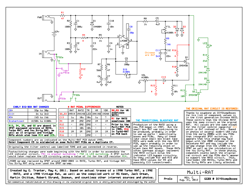
Could anyone tell me what are the C13 and R15 for?
postlmg.cc
Could anyone tell me what are the C13 and R15 for?
I'm trying to figure out why the RATs sound different from the RAT2s. All my RATs sound clearer and have more clarity.
BTW, I have about 5 early 90s RAT2s right now, all of which have a 22M register (red-red-blue-gold) for R13, not 10M. I also have a RAT which has the RAT2 board, and it has a 2.2M (red-red-green-gold) for the same spot. I believe it's just for the LED circuit, so not a big deal perhaps?
Thanks in advance.
multi rat clear — Postimages
I'm trying to figure out why the RATs sound different from the RAT2s. All my RATs sound clearer and have more clarity.
BTW, I have about 5 early 90s RAT2s right now, all of which have a 22M register (red-red-blue-gold) for R13, not 10M. I also have a RAT which has the RAT2 board, and it has a 2.2M (red-red-green-gold) for the same spot. I believe it's just for the LED circuit, so not a big deal perhaps?
Thanks in advance.

Last edited:
")
