Pauleo1214
Well-known member
Does anyone know where to splice in the anode and cathode on the circuit to get a rate indicator led? Any help would be greatly appreciated!
Best,
Paul
Best,
Paul

Thank you Cybercow! Nice to see you on this board!Across R7 (in parallel with it). The cathode goes to Q2 (pin #1 of the 2N2646) and the anode goes to the other side of R7. R7 'might' need to be increased to 1K. Socket-n-see. Good luck.
Just a follow up, it does work. You did mean across R9 and Q3, right?Thank you Cybercow! Nice to see you on this board!
I mean precisely R7 and Q2 according to the PedalPCB Woodpecker schematic. But it seems PedalPCB has changed up their BOM and schematic since I'd built mine. So here's a screenshot of the schematic I used in my older version where R7 and Q2 are referenced. . . . .Just a follow up, it does work. You did mean across R9 and Q3, right?

Just wanted to circle back and confirm it works and thank you! I hate to be a PITA but I have a follow up question; the LED pulses at almost full brightness. Is there a value resistor you recommend between the anode and R6 that might exaggerate the pulsing effect?I mean precisely R7 and Q2 according to the PedalPCB Woodpecker schematic. But it seems PedalPCB has changed up their BOM and schematic since I'd built mine. So here's a screenshot of the schematic I used in my older version where R7 and Q2 are referenced. . . . .
View attachment 22800
Note how the Rate LED has been added to the schematic. It will go in the same topological location on your build.
For the newer version, it would appear that rate LED would go across R6 with the cathode connected to pin #2 of the 2N6027. No need to modify the value of R6.
The Woodpecker can be built with either a PUT (2N6027) or a UJT (2N2646) - providing a couple other adjustments are made and the pinouts between the PUT and UJT are compensated for. The earlier version I have uses the 2N2646 UJT. And it appears that PedalPCB has changed up the schematic & BOM for using the easier to get 2N6027 PUT.
So, you can put a rate LED across R6 with the cathode connected to pin #2 of the 2N6027.
Yeah, adding a CLR in series with the Rate Indicator LED should do well to diminish the brightness.Just wanted to circle back and confirm it works and thank you! I hate to be a PITA but I have a follow up question; the LED pulses at almost full brightness. Is there a value resistor you recommend between the anode and R6 that might exaggerate the pulsing effect?
B
So I just added this in a combo build. It fired up and instantly heard (and smelled) the blown LED. I added a 2k2 CLR off R6 and the anode. The entire combo audio works, but any idea what to do/what I may have done wrong?Yeah, adding a CLR in series with the Rate Indicator LED should do well to diminish the brightness.
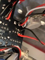
Dunno. Did you strap the LED in parallel with R6? Can't see what you did. Good, clear pic or two would help.So I just added this in a combo build. It fired up and instantly heard (and smelled) the blown LED. I added a 2k2 CLR off R6 and the anode. The entire combo audio works, but any idea what to do/what I may have done wrong?
Honestly, in this context, I’m not too sure. I just ran a black wire off Q2 pin 2, red wire off R6 and attached the led black cathode, red anode and CLRDunno. Did you strap the LED in parallel with R6? Can't see what you did. Good, clear pic or two would help.
HmmmmYou should need only to strap the Rate LED across R6; with the cathode on the Q2 side.
 isnt that what I did? When you say across R6, are you saying attached to BOTH legs of R6?
Not according to the pic you've posted.Hmmmm
Yes. Precisely. Across both ends of (in parallel with) R6.When you say across R6, are you saying attached to BOTH legs of R6?

Thank youYes. Precisely. Across both ends of (in parallel with) R6.