Resolved: Anyone with Compandor Experience?

andrewsrea

Active member
My DoD Chorus 690 wasn't working. The LFO, Flip-flop SAD512D bucket-brigade chip and the compression half of the NE571 compandor was operating, but the expansion wasn't and the Vcc was about +14.2VDC (below the threshold of the LM78L15 regulator). I assumed the electrolytics were all bad and replaced them all, ensuring exact polarity (and quadruple checking).

The Vcc came back to a perfect +15.04VDC and then I could not get output from the NE571 from either the compression 'send' or the expansion 'return'. I bought a NOS NE571 from Small Bear and had the same problem. I've checked all associated circuit values and continuity, multiple times. No luck. 30 hours later and I am out of ideas.

FWIW: the compression and expansion circuits employed are straight out of the NE571 Compandor data sheet.

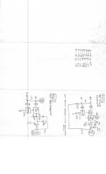
Attached is the DoD schematic, a diagram of the NE571 schematic and its pin voltages. All look textbook, except the compressor output is very high at 14.41v (pin 10) and the expander output (pin 7) appears high at 7.94v. I noticed the design doesn't have a 1M resistor off the output to keep the caps from DC loading, but keep telling myself the original design worked.

Any ideas or solutions would be appreciated.


DoD 690 Chorus - marked.jpg DoD 690 Chorus - compandor.jpg
 

Attachments

  • DoD 690 Chorus - compandor.jpg
    DoD 690 Chorus - compandor.jpg
    161.8 KB · Views: 2
I just posted a pic of 690 in the let’s see your pedalboard thread, and this was the next thing I clicked on. What are the chances?

I’ve got no input on your question, but I’d be willing to measure something on mine if that’s helpful. I haven’t had it long. It’s a little noisy, but seems functional.

Most appreciated. The device in question is the NE571 IC. A reading of DC voltage to ground for all the 16 pins would be extremely helpful, in conjunction with the info @bean kindly gave!

I've had this pedal since 1986, as it was gifted to me by a friend who was terminally ill. One of those things that it was working fine 4 years ago when I shelfed it and did not work when I took it out a few weeks ago.

BTW: please send the link of your pedalboard pic!
 

That is extremely helpful and ties into what @bean provided! Thank you!

Indeed, my only problem appears to be pin #10 where I am over voltage by 8v to 9.5v. Per Bean's advice, I am going to rebuild the 33k resistors and 10uF cap at pins #10 & #12.

I can tell from your gut-shot, that your pedal is all original and by pin #13, your electrolytics for the power supply are still in tolerance enough to sustain 15v through the regulator. I also see that your variant has the 10K resistor connected to the 4.7uF cap (from pin #14 & #15) to the 0.1uF cap, connected to pin #6 of the SAD512D. That 10K resistor isn't drawn on the schematic, but i found it on my version as well.
 
@Erik S , one more thing: be careful of handling the lead wires. Many pedals of this era used aluminum wire and soldered with acid-rosin solder. It corrodes the wire at the joint and they easily break off, or look connected but are actually hanging by threads. I've found this same condition on MXR, Ross and DoD pedals of this era.
 
@Erik S , one more thing: be careful of handling the lead wires. Many pedals of this era used aluminum wire and soldered with acid-rosin solder. It corrodes the wire at the joint and they easily break off, or look connected but are actually hanging by threads. I've found this same condition on MXR, Ross and DoD pedals of this era.
That’s a good tip. Thanks.

I don’t have any immediate plans of tearing into this one, but I’ll be gentle if I do.

I did wonder for a minute about what it would take to get it running on dc (maybe 18v)? But that’s so far down the to-do list I’ll never actually get there.

Mine also has some sentimental value tied to it’s first owner, so I’ll keep it around, but I don’t think it’ll be my go-to chorus.

Keep us updated on your progress - I’m definitely interested to hear how it turns out.
 
@Erik S , this would easily run on 18 VDC and I am guessing 40ma. Just undo the diodes and insert the 18 VDC in one of the holes, at the 470uF cap. Then just undo the AC clips, the strain relief and then use a plastic hole cover.

I was thinking converting to true bypass, as it has tone suck. This would require relays vs a TPDT switch, as the latter would require surgery on the PCB. Always torn between keeping it authentic vs. practical.
 
RESOLVED:
Thanks to @bean and @Erik S, I resolved the original problem. The short story is, the schematic was drawn incorrect. It had the (-) polarity of the 4.7uF cap facing pin #10, when it should have been facing pins #15 & #16. This corrected the pin voltages.

The original NE571 compandor did not work, so I installed the new one and it now does the chorus effect.

I am going to start a new thread, as it performs like new as long as there is signal passing through. The second you stop, it begins popping at about one pop per 1.5 seconds. This goes away when the 'Depth' is off. Tomorrow is another day to take that on.
 
Back
Top