Chuck D. Bones
Circuit Wizard
This time we'll talk about output characteristics and distortion.
Bear with me while I digress a bit and explain class-A, class-B, and push-pull. In the simplest terms, class-A means that the amplifying device, in the case of opamps it's a transistor, is always in conduction. In other words, the collector (or drain) current never goes to zero. A single-ended tube amplifier, like the Fender Champ, runs the output stage class-A. Class-A is not efficient, it's not particularly powerful, but it's simple and has a sweet tone. When amplifier builders wanted to get more power and efficiency, push-pull was born. With push-pull, two (or more) devices share the load. One device drives the load on the positive half-cycle of the signal, the other drives the load on the negative half-cycle. VOX AC15 & AC30 amplifiers run the push-pull output tubes class-A. It's more efficient than single-ended, but there is a way to get even more power and efficiency. That way is to run the output devices class-B. In class-B, when one device is driving the load, the opposite device is completely off. Right at the zero-crossing of the waveform, one output device switches off and the other switches on. since it is not possible to do this perfectly, there is no such thing as a true class-B output stage. Instead, the output devices are biased so that near the zero-crossing, both devices are in conduction. This is called class-AB. For small signals, both sides of the push-pull output drive the load, class-A style. As the signal gets larger, one of the devices turns off and we're running class B. The Fender & Marshall push-pull amps run class-AB.
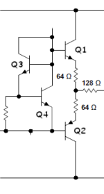
With me so far? Now we can talk about opamp output stages, which are, as you may have guessed by now, push-pull class-AB. Here's a typical opamp output stage. Q1 & Q2 are emitter-followers that drive the output pin. Those 64Ω resistors are part of the bias circuit. They also provide short-circuit protection that keeps the opamp from burning up if we short the output to ground or Vcc. Q3 & Q4 are also part of the bias circuit. They maintain a constant voltage between Q1-B and Q2-B, which keeps Q1 & Q2 biased class-AB. Because all four transistors are on the same die, they are very close to the same temperature, which stabilizes the bias over the entire operating temperature range. Other transistors in the opamp (not shown) drive Q1 & Q2. Most opamps limit their output current to something between 10mA and 50mA. We don't want to run anywhere near that limit, or else clipping can occur. The transition between class-A and class-B is fairly smooth, but not perfect because the current gain of the output stage is different depending which transistor (or both) is driving the output. The non-uniform current gain causes cross-over distortion. Opamps rely on negative feedback to reduce the distortion. Expensive opamps like the OPAx134 series go to a lot of trouble to minimize distortion in the output stage by balancing the transistors and running the bias fairly high. There is a trick we can play to keep the output stage running class-A. Take a look at the Dark Esbat schematic. Ever wonder what R5 & R15 do? They draw DC current from the output stage in an effort to encourage Q1 to run class-A all the time.

Now let's talk about output voltage swing. Q1 & Q2 are emitter followers, which means the output can't get any closer to the rails than one diode drop. That's with zero load current. The circuits that drive Q1 & Q2 can't drive their bases to the rails either. The result is we're lucky if we can get withing 2V of either rail. An opamp running on 9V can't be expected to swing the output more than 5Vp-p.
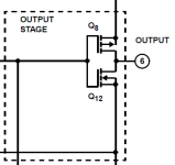
Some opamps can get all the way to the rails. They use a different output structure. Here is the output stage of a CA3130. This is typical of CMOS opamps. Note that Q8 & Q12 are not source-followers. Their sources are tied to the rails and their drains connect to the output pin. These can drive within a few mV of the rails as long as the current load is fairly light. Unlike the emitter follower output, this output stage has gain (typically 10x) and a high output impedance when it's not clipping. Because of all that, it is sensitive to loading. Feedback helps, but we still have to be careful because this type of output stage is not happy driving a heavy load, like a Rat's clipping diodes for instance. This output stage has another drawback. When it's running in class-A mode, the DC current thru Q8 & Q12 is fairly high, several mA, and it drops way down when the output stage goes into class-B. This can introduce current ripple into the power rails, which requires a lot of filtering to keep from upsetting other parts of the circuit. Used properly, this type of output stage shines. The clipping is very symmetric. That's why Bjorn Juhl uses it in some of his circuits.

That's all for now. Next time: slew rate, bandwidth and feedback.
Bear with me while I digress a bit and explain class-A, class-B, and push-pull. In the simplest terms, class-A means that the amplifying device, in the case of opamps it's a transistor, is always in conduction. In other words, the collector (or drain) current never goes to zero. A single-ended tube amplifier, like the Fender Champ, runs the output stage class-A. Class-A is not efficient, it's not particularly powerful, but it's simple and has a sweet tone. When amplifier builders wanted to get more power and efficiency, push-pull was born. With push-pull, two (or more) devices share the load. One device drives the load on the positive half-cycle of the signal, the other drives the load on the negative half-cycle. VOX AC15 & AC30 amplifiers run the push-pull output tubes class-A. It's more efficient than single-ended, but there is a way to get even more power and efficiency. That way is to run the output devices class-B. In class-B, when one device is driving the load, the opposite device is completely off. Right at the zero-crossing of the waveform, one output device switches off and the other switches on. since it is not possible to do this perfectly, there is no such thing as a true class-B output stage. Instead, the output devices are biased so that near the zero-crossing, both devices are in conduction. This is called class-AB. For small signals, both sides of the push-pull output drive the load, class-A style. As the signal gets larger, one of the devices turns off and we're running class B. The Fender & Marshall push-pull amps run class-AB.
With me so far? Now we can talk about opamp output stages, which are, as you may have guessed by now, push-pull class-AB. Here's a typical opamp output stage. Q1 & Q2 are emitter-followers that drive the output pin. Those 64Ω resistors are part of the bias circuit. They also provide short-circuit protection that keeps the opamp from burning up if we short the output to ground or Vcc. Q3 & Q4 are also part of the bias circuit. They maintain a constant voltage between Q1-B and Q2-B, which keeps Q1 & Q2 biased class-AB. Because all four transistors are on the same die, they are very close to the same temperature, which stabilizes the bias over the entire operating temperature range. Other transistors in the opamp (not shown) drive Q1 & Q2. Most opamps limit their output current to something between 10mA and 50mA. We don't want to run anywhere near that limit, or else clipping can occur. The transition between class-A and class-B is fairly smooth, but not perfect because the current gain of the output stage is different depending which transistor (or both) is driving the output. The non-uniform current gain causes cross-over distortion. Opamps rely on negative feedback to reduce the distortion. Expensive opamps like the OPAx134 series go to a lot of trouble to minimize distortion in the output stage by balancing the transistors and running the bias fairly high. There is a trick we can play to keep the output stage running class-A. Take a look at the Dark Esbat schematic. Ever wonder what R5 & R15 do? They draw DC current from the output stage in an effort to encourage Q1 to run class-A all the time.

Now let's talk about output voltage swing. Q1 & Q2 are emitter followers, which means the output can't get any closer to the rails than one diode drop. That's with zero load current. The circuits that drive Q1 & Q2 can't drive their bases to the rails either. The result is we're lucky if we can get withing 2V of either rail. An opamp running on 9V can't be expected to swing the output more than 5Vp-p.
Some opamps can get all the way to the rails. They use a different output structure. Here is the output stage of a CA3130. This is typical of CMOS opamps. Note that Q8 & Q12 are not source-followers. Their sources are tied to the rails and their drains connect to the output pin. These can drive within a few mV of the rails as long as the current load is fairly light. Unlike the emitter follower output, this output stage has gain (typically 10x) and a high output impedance when it's not clipping. Because of all that, it is sensitive to loading. Feedback helps, but we still have to be careful because this type of output stage is not happy driving a heavy load, like a Rat's clipping diodes for instance. This output stage has another drawback. When it's running in class-A mode, the DC current thru Q8 & Q12 is fairly high, several mA, and it drops way down when the output stage goes into class-B. This can introduce current ripple into the power rails, which requires a lot of filtering to keep from upsetting other parts of the circuit. Used properly, this type of output stage shines. The clipping is very symmetric. That's why Bjorn Juhl uses it in some of his circuits.

That's all for now. Next time: slew rate, bandwidth and feedback.

