Roger Mayer Octavia

Chuck D. Bones

Circuit Wizard
I almost managed to build this to the stock specs. Then I read Roger Mayer's advert for the Vision Octavia, so I made one of those (or something close to it) instead. I tried to copy the look of the Vision Octavia as well.
The Real Deal:
Roger Mayer Vision Octavia (sm).jpg

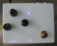
Mine. I'm out of chrome stomp switches at the moment. Same control layout as the RM version. Dials are set for clean octave (ok, as clean as you can get with one of these) and unity gain.
Octavia III - front 02.jpg

Hamish, I was thinking of you when I laid out the insides:
Octavia III - innards 02.jpg

The added TONE pot is hiding under the board. Sounds pretty good. Different from the Foxx Tone Machine. The TONE control is helpful in bringing the octave back into focus at higher DRIVE settings. Except for the TONE control, it's a faithful reproduction of the Octavia II, the one that looks like a space ship.
 
I almost managed to build this to the stock specs. Then I read Roger Mayer's advert for the Vision Octavia, so I made one of those (or something close to it) instead. I tried to copy the look of the Vision Octavia as well.
The Real Deal:
View attachment 4268

Mine. I'm out of chrome stomp switches at the moment. Same control layout as the RM version. Dials are set for clean octave (ok, as clean as you can get with one of these) and unity gain.
View attachment 4269

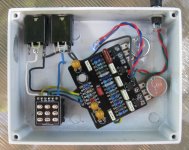
Hamish, I was thinking of you when I laid out the insides:
View attachment 4270

The added TONE pot is hiding under the board. Sounds pretty good. Different from the Foxx Tone Machine. The TONE control is helpful in bringing the octave back into focus at higher DRIVE settings. Except for the TONE control, it's a faithful reproduction of the Octavia II, the one that looks like a space ship.
Sweet!!!
Does it sound as good as it looks?¿
 
I think it does. Nice octave tone on the higher strings, above the 9th fret. Very dynamic. Not much compression, compared to the Tone Machine.
 
My original plan, when I decided to place the knobs like they are on the RM Vision Octavia, was to use one pot with PC pins to support the board and use solder-lug pots for the other two controls. Then it hit me: just angle the board. I knew you'd appreciate it.
 
Very nice! Would you mind posting a link or schematic how you spliced the tone control in? Cheers!
 
I'll describe it briefly here, and then post the details in the Mods forum tomorrow.

There is a 47K resistor on the board, it's part of the gain stage feedback loop. I put an A100K and a 6.8nF cap in series, and connected those two parts in parallel with the 47K resistor. The TONE pot is wired so the resistance goes up when it's turned CW. It's possible that the 6.8nF cap should be even larger, say 10nF. I soldered one lead of the cap to pin 1 of the pot terminals, attached wires to the other cap lead and pin 2 of the pot and used heatshrink to insulate and support everything. Then I soldered the other ends of the wires to the backside of the board, at each end of the 47K resistor.
 
Back
Top