@giovanni -
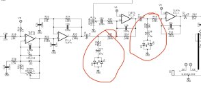
What I meant by the voltage divider (probably poor choice of words) was there are 2 paths, thru the 100k to the opamps or thru the LEDs to ground. The signal will flow thru the path of least resistance. For audible frequencies, (1) low voltage signals pass onto the opamp, while (2) when the when the instantaneous voltage exceeds the threshold voltage of the LEDs, then the signal shunts to ground. There is rounding of the corner there set by the voltage-dependent LED resistance (∂V/∂I) + the series 6.2k or 10k resistor.
And by compression, I meant it compressed the peaks once the LED threshold voltage was approached. It's not an abrupt clip, but is rounded over a small range of voltages which is equivalent to nonlinear compression. You called it clipping, same thing.