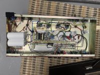
Simms-Watts AP100 mkII 1972

JohnnyCreepy

Well-known member
Start of the story.

Couple years ago I was on hunt for a new amplifier and found Simms-Watts AP100 sale nearby. Amp was in good shape, played regulary and power side was recapped within 10 years. Majority of the components were original and circuit compared to schematic available.

Topology was two channels both with their own plate driven TB tone stacks, followed by two gain stages before LTP and ultralinear power amp with EL34.


IMG_6126.jpeg

Played few months with it before one power tube gave up and started modding this thing. To be continued.
 
Last edited:
Played few months without bigger problems. Accuired 2x15” speakers and they revealed a need to reduce PA coupling cap values. OTX pushes lows efficiently to the point overexcursion was happening with modern speakers. Also grid blocking was occuring. Blocked spkr cab’s reflex ports and reduced PA coupled from 100nf to 22nf. Was all good for a while.

So the first bigger problem came when year 2025 started. One of the power tubes gave up and went dud with a cool zap. Fly high in tube heaven with your C-wings you poor SED EL34 tube! 👼

So it was new power tube time and matched quartet of JJ EL34s went in. Also beefed up wattage for resistors around tubes. Changed power supplys first pair of big can 240uF electros which were the original ones. :cool:

Notice the safety of the original build with with exposed HV connections. And yeah, when chassis is in amp cab EXTRA attention is needed when doing tube rolling…
IMG_6035.jpeg

To be continued with HUM, tweaks and rebuilds…
 
I just made a long post about last year tinkering with the amp, but accidentaly closed my browser window. Poof, all gone. Shit.

So let’s keep this short:

1. ruined vintage value with new caps and resistors

IMG_6709.jpeg

2. Hum and pcb falling apart bothers - rebuild on tag strips with first timers messy looking layout
IMG_7595.jpeg

3. Hum still bothers and second channel feels bit useless - rebuild like Model-Tish

IMG_8152.jpeg

After last pic there’s been small changes like input resistors, fine tuning layout and wiring

And it sounds like this. https://on.soundcloud.com/ZF55qVirSzezMZGGEa
 
Send it to Robert to trace 😂
Pcbs would be named ”Model Tea&Biscuits”?

Oh and latest build mostly solved hum problem. It was either reducing grid leak values from 200K to 126K or amount of NFB fed to PI. Also ditched shielded input wiring to V1 grid and raised stoppers from 10K to 40-50K. Response for dirt pedals is now better.
 
Could you diagnose where the hum came from before the changes btw? I would say a shielded input to v1 grid stopper is mandatory. Raising the grid stoppers probably did a lot for you there.
 
Could you diagnose where the hum came from before the changes btw? I would say a shielded input to v1 grid stopper is mandatory. Raising the grid stoppers probably did a lot for you there.
It was happening on somewhere between V2 and PI+NFB.

NFBs first resistor from speaker feed has a pot wired as variable resistor series onto it. If I turn pot to reduce NFB amount the hum is more aubile. Now the NFB section is valued 20K resistor+50K (or was it 100K pot) from 16 ohm to 10K resistor parallel with cap leading to second lug of a 10K pot. So maybe that?

To be honest exact reason hasn’t revealed for me. Heaters are elevated, NFB feed is shielded etc. But currently my mains freq hum is low enough to keep me satisfied for a while.

Gonna just play with the amp for a while, but next time when chassis is opened I should raise heater elevation DC voltage from 50 to near 100v to make sure CF tubes c/k limit isn’t exceeded and feed elevation from PI power feed instead of the first cap leading to OT primary CT.
 
Is the amp close to an EM source when you play? Computer, monitor etc? From your layout picture, I would say that probably plays a huge role as well. Seems you have your grid stoppers on the pins though so there is that already.
 
Have you tried chopsticking the preamp wires to see if you can find one that’s causing the hum and buzz?

1950 rules of wire dressing states that wires should cross at a 90° angle or as close as possible and that parallel wire should be avoided to avoid coronal discharge into previous gain stages
 
Is the amp close to an EM source when you play? Computer, monitor etc? From your layout picture, I would say that probably plays a huge role as well. Seems you have your grid stoppers on the pins though so there is that already.
Have you tried chopsticking the preamp wires to see if you can find one that’s causing the hum and buzz?

1950 rules of wire dressing states that wires should cross at a 90° angle or as close as possible and that parallel wire should be avoided to avoid coronal discharge into previous gain stages
⬇️
After last pic there’s been small changes like input resistors, fine tuning layout and wiring
So yeah, stickchops, 90 degree zig zags etc have been tried. There’s distance and 90 degree crossings which aren’t so obvious from a pic. And yeah, after the pic wiring is tidier and some changes there too. The same hum problem was there with the original PCB before I touched any offboard wiring!

I’ve been looking ideas and possible solutions from guitar amp and hifi sides of tube amp building. Things what I haven’t done are opening PTs end bells to peel inside or isolating PT from chassis with rubber spacers. Also PI snubber across plates hasn’t been tried, but what I understand it really shouldn’t affect low freqs like the 60-120Hz hum I have there.

Apart from mechanical source the NFB is what I suspect as hum is more audible when there’s more feedback fed to PI. Maybe it’s mechanical vibration from TXs picked by tube or piezoelecric wire like the shielded NFB wire?
 
Last edited:
⬇️

So yeah, stickchops, 90 degree zig zags etc have been tried. There’s distance and 90 degree crossings which aren’t so obvious from a pic. And yeah, after the pic wiring is tidier and some changes there too. The same hum problem was there with the original PCB before I touched any offboard wiring!

I’ve been looking ideas and possible solutions from guitar amp and hifi sides of tube amp building. Things what I haven’t done are opening PTs end bells to peel inside or isolating PT from chassis with rubber spacers. Also PI snubber across plates hasn’t been tried, but what I understand it really shouldn’t affect low freqs like the 60-120Hz hum I have there.

Apart from mechanical source the NFB is what I suspect as hum is more audible when there’s more feedback fed to PI. Maybe it’s mechanical vibration from TXs picked by tube or piezoelecric wire like the shielded NFB wire?
So what kind of volume level is the hum?

Are you talking audible once the drummer kicks in?

'cuz 100w is stadium level loud.... I wouldn't sweat it if it's only at low volume. My AB763 Twin has significant hum at low volume, my AB763 vintage SFDR has very little.
 
View attachment 117754
This was original circuit and it was audible enough. After rebuilds I’d say it’s slightly audible. So from my perspective it doesn’t bother anymore.
Just taking a quick look at the amp...

Those ceramic capacitors on top of the chassis will make hum and buzz, as do carbon comp resistors but I didn't see any of those tho.

Johnson-Nyquist noise is more prominent when the wattage in a resistor is close to it's rating, and why I use 1w resistors minimum in the preamp.

Rock On!
In most recent build even the tone stacks silver micas got replaced with polys. There nothing ceramic there apart tube sockets and resistor shells!
 
Updated and fixed layout problems with few circuit changes.

  • Diode bridge for bias, bigger supply caps and 2W heavy duty 10K pots for adjustment
  • Moved HTR elevation tap to PI supply node
  • Removed presence pot
  • Reduced PI and preamp voltages
Constant hum getting louder when opening master vol was reduced with these. Still giving some of that low hum and I’m left with these things to consider:
  • Steel chassis with magnetic coupling from trafos or their orientation
  • Magnetic flux leak on OT (common with Williamson UL-design and worn/cheap trafos)
  • Sensitivity to slight unbalance on bias. Individual bias adjustment for all 4 tubes needed?
  • Instead using heater center tap maybe elevated humdinger could do the trick
IMG_8744.jpeg
 
Last edited:
Shameless bump about the plan for this week. Hum was greatly reduced with last weekend tweaking the layout, but I’d still like to try to get rid of it.

⏺️V1 cathodes share 680r/1uF on normal & bright channels. Not enough volume on bright channel. Forum lore sources state some have experienced problem with weird cathode filament leakage hum resolving with bigger bypass cap.
➡️Split V1a+b cathodes. Make bypass caps bigger and hope hum reduce as side effect.

⏺️Filament DC elevation is now at 22.7V after moving it for the PI tap from the first power supply cap.
➡️Tweak first resistor on voltage divider and aim for 40-50Vdc.

⏺️Chassis is steel and OT might cause hum via chassis. Bolts helding lamination together are not insulated. One leg has a crack quick fixed with metal epoxy.
➡️Add rubber sheet between OT and chassis. Insulate bolts with heat shrink. Make leg crack fix proper and more permanent with welding machine.

⏺️Filament leads on preamp are not in phase.
➡️Flip leads on V2.

⏺️PTs sec side filament leads are with CT and voltages seem to be balanced on DMM measurement, but artificial tap with humdinger and elevation could be worth a try.
➡️Disconnect filament CT to try an artificial one.

⏺️EL34 grid stoppers are 5W type power resistors and might have noticable inductance.
➡️Replace grid stoppers with 10K metal film resistors. This also reduces probality for grid blocking when preamps cathode bypass caps get bigger.
<- I didn’t recall there’s 17K ones already in. I’m sure they aren’t matched closer than a lucky shot with 5% factory tolerance.
 
Last edited:
Had time to tweak things on this. First raised heater elevation voltage to 60VDC and added 50r resistor between filament CT and voltage divider. Then proceeded making a proper star ground and moving OneTrueGround straight to first filter cap negative side. Also made sure gnd leads are connected more into negative side of preamp supply caps.

Also separated input tubes cathodes. Now there’s 1K/22uF on both side of first stage.

Revisited grounding scheme with a big lump of gnd leads and solder into one-true-gnd star point isn’t pretty, but hell, it works. Combination of 50&100Hz hum was greatly reduced on lower freqs and now it started to sound more like a residue of voltage buzz if you know what I mean.

I’ll do some tube roll today evening to see if the lowered hum is from cathode-heater filaments before adjusting OT-chassis connection and adding insulation layer of rubber sheet between trafo standoffs and chassis.
 
heck yeah star ground for the win 🤟🏻
Solder grease was essential for plumbing…lumping six 18-22awg single core copper wires together. In past I had tried star gnd in this amp, but lesson learned about really doing a single point and not relying on star made to a bolt on chassis…
 
Back
Top