SOLVED Simple Jfet Buffer

Status
Not open for further replies.

dstahl

New member
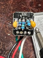
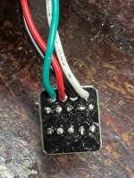
I was planning on building a dual buffer for my pedal chain using the simple jfet buffer pcb's.
When I was checking my first one for testing I noticed a considerable volume drop. I get sound. But it is way lower than just plugging in guitar direct. It did not sound like unity gain.
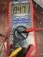
When I took voltage readings on the MMBFJ201 I got
S 9.4 V
D 75 MV
G 0.6 V

Any thoughts on where I should be looking?
 

Attachments

  • IMG_1139.JPG
    IMG_1139.JPG
    85.3 KB · Views: 28
  • IMG_1140.JPG
    IMG_1140.JPG
    76.4 KB · Views: 28
  • Like
Reactions: fig
I have green as input and white as output. red and black are +/-
So that should correspond to the build doc. and board had no silk screening for pin out. so maybe it is an updated version.
That all sounds correct. right?
 
you are correct. I got this pack from Tayda . but when I just measured it it was 47ohm. I used to meticulously test. I guess I need to go back to that. Will try it with the correct resistor and hopefully it will all be good.
 

Attachments

  • IMG_1143.JPG
    IMG_1143.JPG
    256.7 KB · Views: 12
  • IMG_1142.JPG
    IMG_1142.JPG
    254.9 KB · Views: 12
That was it @Stickman393 . Thank you so much for spotting that. It is way closer to the same volume when plugged in direct to the amp.
I did replace the 2.2k resistors with a 2k. do you know if that would cause a bit of volume drop? I noticed it is is just slightly louder with more dynamics when plugged in direct, vs going through the buffer. But maybe that is normal for the circuit.
2.2m vs 2m, we're talking less than a 10% shift in value...a tolerance which used to be a pretty common in carbon comp resistors and such.

Looks like the two 2.2Ms are part of a voltage divider feeding the gate of the JFET, which will yield the same voltage at the gate regardless of values used.

It would seem to make sense that the 47 ohm is the culprit here...increasing the resistance between your ground and your output should make for a larger difference in potential between those two points, thus a stronger signal.

I would love to talk a little bit about input and output impedance...if I understood it better. Simple circuit. High input impedance, low output impedance. I'm just gonna drop those words and make it seem like I know my stuff.
 
  • Love
Reactions: fig
Status
Not open for further replies.
Back
Top