
You are using an out of date browser. It may not display this or other websites correctly.
You should upgrade or use an alternative browser.
You should upgrade or use an alternative browser.
Simplest relay bypass possible - no microcontroller
- Thread starter ADAOCE
- Start date
FancyEspresso
Member
Thank you!!
megatrav
Well-known member
Is this the same for latching and non-latching?R1 10K
R2 10K
R3 100K
R4 10K
R5 1K
C1 1u MLCC
C2 1u MLCC
D1 1N5817
D2 1N5817
D3 1N5239B
IC1 NE555
K1 Relay (A-4.5W-K)
Q1 2N3904
Q2 2N3904
FS Momentary Footswitch
Robert
Reverse Engineer
That list is for non-latching only.
This is the parts list for the latching relay version:
R1 10K
R2 10K
R3 100K
R4 10K
R5 10K
R6 10K
C1 1u MLCC
C2 100n
C3 100u
C5 100n
IC1 NE555
IC2 78L09
K1 Relay (TQ2-L-5V)
Q1 2N3904
Q2 2N3904
Q3 2N3906
Q4 2N3904
FS Momentary Footswitch
This is the parts list for the latching relay version:
R1 10K
R2 10K
R3 100K
R4 10K
R5 10K
R6 10K
C1 1u MLCC
C2 100n
C3 100u
C5 100n
IC1 NE555
IC2 78L09
K1 Relay (TQ2-L-5V)
Q1 2N3904
Q2 2N3904
Q3 2N3906
Q4 2N3904
FS Momentary Footswitch
GuitarBuilder
New member
Now we're getting to the most interesting question!Hey Guys, with a Simple Relay Bypass PCB (latching), we can hear some "pop" noise when clicking switch?
@PedalPCB : any chance of developing a version with a photoMOS mute switch?
GuitarBuilder
New member
Sorry about the late question! I'm a big fan of the µP-controlled bypass, so I'm having difficulty understanding why someone would want a "simpler version". My question to @PedalPCB is: does the 555 timer version suffer from mis-triggering when the foot switch is depressed for too long? The µP version appears to be flawless and fool-proof.Took a little longer than expected, but two versions are on the way.
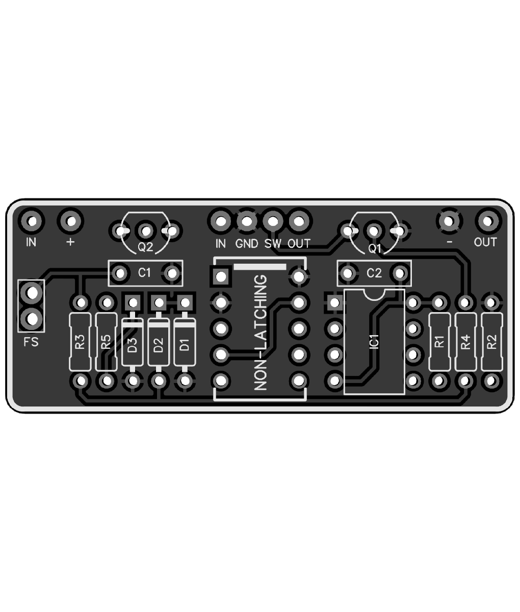
This one uses a standard non-latching mini relay.
(Higher power consumption, but less expensive)
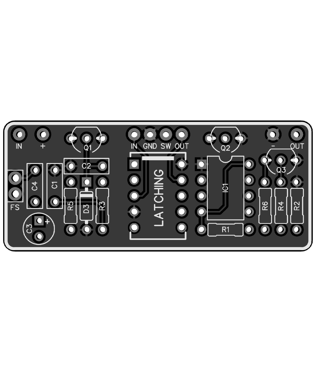
This one uses a latching mini relay.
(More expensive, but less power consumption)
Just want to reconfirm the resistor value. On the PCB it calls for two 1k resistors. Is this correct or should I go with your parts list which calls for 10k instead. Thanks.R1 10K
R2 10K
R3 100K
R4 10K
R5 1K
C1 1u MLCC
C2 1u MLCC
D1 1N5817
D2 1N5817
D3 1N5239B
IC1 NE555
K1 Relay (A-4.5W-K)
Q1 2N3904
Q2 2N3904
FS Momentary Footswitch
Attachments

I was posing the question because I was building a loop strip switcher and didn’t need intelligent functionality and was trying to minimize cost is all.Sorry about the late question! I'm a big fan of the µP-controlled bypass, so I'm having difficulty understanding why someone would want a "simpler version". My question to @PedalPCB is: does the 555 timer version suffer from mis-triggering when the foot switch is depressed for too long? The µP version appears to be flawless and fool-proof.
SYLV9ST9R
Well-known member
Thanks, came here to ask the same!Just want to reconfirm the resistor value. On the PCB it calls for two 1k resistors. Is this correct or should I go with your parts list which calls for 10k instead. Thanks.
One other stupid question, which 1K to replace with 10K? Or should I replace both with 10K? Thanks!!The PCB was originally designed for 1K, which will work fine, but 10K will consume less idle current.
Go with 10K if you have them, if not, it'll function exactly the same with 1K.
having a helluva time finding thatThat list is for non-latching only.
This is the parts list for the latching relay version:
R1 10K
R2 10K
R3 100K
R4 10K
R5 10K
R6 10K
C1 1u MLCC
C2 100n
C3 100u
C5 100n
IC1 NE555
IC2 78L09
K1 Relay (TQ2-L-5V)
Q1 2N3904
Q2 2N3904
Q3 2N3906
Q4 2N3904
FS Momentary Footswitch
I have been looking everywhere for a "L8709" variety IC chip. Is this supposed to be Q5? I'm seeing 3 leg transistors, but no IC'sThat list is for non-latching only.
This is the parts list for the latching relay version:
R1 10K
R2 10K
R3 100K
R4 10K
R5 10K
R6 10K
C1 1u MLCC
C2 100n
C3 100u
C5 100n
IC1 NE555
IC2 78L09
K1 Relay (TQ2-L-5V)
Q1 2N3904
Q2 2N3904
Q3 2N3906
Q4 2N3904
FS Momentary Footswitch
Robert
Reverse Engineer
L78L09ACZ L78L09 78L09 +9 VOLTS 100mA Voltage Regulator IC
SGS THOMSON - Get It Fast - Same Day Shipping
 www.taydaelectronics.com
Super cool. I ordered a bunch incase that was right because they were cheap. I ordered 5 of the relays and 5 boards for the latching.L78L09ACZ L78L09 78L09 +9 VOLTS 100mA Voltage Regulator IC
SGS THOMSON - Get It Fast - Same Day Shipping
Looking forward to getting them built and installed in a couple of things this weekend.
I know the build docs aren't out yet but the layout seems pretty simple. In and out is self explanatory, are + and - coming off the power jack?
Any tips on combining it with my informant "buffered or true bypass on a switch layout? Another user here was able to hook me up with a layout for the buffered bypass on the relay switch, but was hoping i could retain my layout.

What happens if power is removed while the pedal is engaged? Will the latching version switch back to bypass to allow signal through?That's basically it. Functionally they both behave exactly the same.