Robert
Reverse Engineer
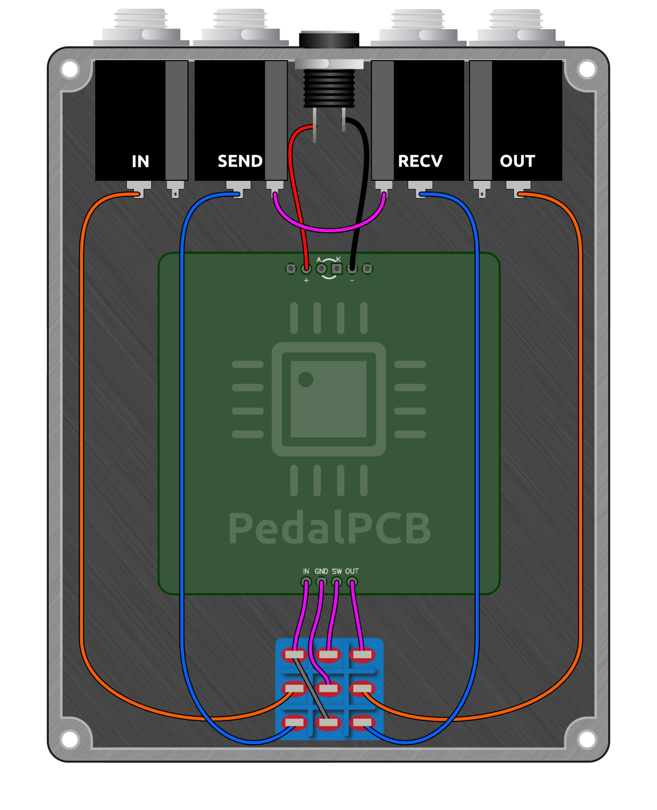
I've had a few people ask about adding the switchable loop send / receive jacks to the Skeptical Buffer so here's a quick and dirty diagram.
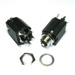
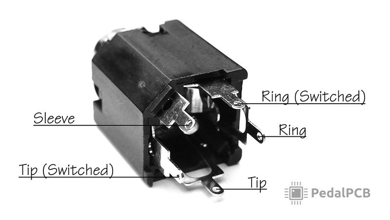
It's pretty simple, you just need 1/4" jacks with switched tip terminals like these (or similar):


Just to keep things clearer this diagram doesn't show the ground wires to the 1/4" jacks so be sure you ground at least one of them.
The orange wires go to the TIP lugs of the IN/OUT jacks, like normal.
The blue wires go to the TIP lugs of the LOOP SEND/RECV jacks.
The purple wire at the top connects the SWITCHED TIP lug of the LOOP SEND to the SWITCHED TIP lug of the LOOP RECV.

It's pretty simple, you just need 1/4" jacks with switched tip terminals like these (or similar):


Just to keep things clearer this diagram doesn't show the ground wires to the 1/4" jacks so be sure you ground at least one of them.
The orange wires go to the TIP lugs of the IN/OUT jacks, like normal.
The blue wires go to the TIP lugs of the LOOP SEND/RECV jacks.
The purple wire at the top connects the SWITCHED TIP lug of the LOOP SEND to the SWITCHED TIP lug of the LOOP RECV.

Last edited:

