Stock GE7 to XTS Version?

"I just orient my non-polar caps so I can read them all on the PCB, and resistor colour coding are in keeping with the PCB's silkscreen beneath them readling left to right."

This is exactly what I did when I did the mod last week. It sounds great.

Thanks
Brian
 
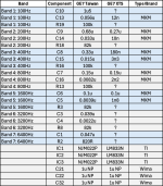
I will add these. The schematic and BOM for the Effects Layouts Prismatic, with the parts mods to turn it into an XTS GE7, which is what I am planning to doing.
Hi all,
I know I’m a bit late on the topic but has anyone made the same table (pic 1) for the GE7 ? Which resistor and capacitor need to be switched with which to reduce the spectrum similarly to the XTS mod ?
 
I am coming back to this thread to say that I have, after a long pedal building hiatus, built the Effects Layouts Prismatic with part subs to make it an XTS version. Seems to operate like the actual XTS one I borrowed last year. I will compare it to my BOSS GE7 but I am already pretty familiar with the frequency range of that one, and this one is definitely not as low or high. I'll report back.
 
Hi all,
I know I’m a bit late on the topic but has anyone made the same table (pic 1) for the GE7 ? Which resistor and capacitor need to be switched with which to reduce the spectrum similarly to the XTS mod ?
I've modified a couple GE-7s using the values that @CR0SSBL4DE and @joelorigo posted (thank you gang, this has been very helpful), and I'm happy to report that I've tested it to work exactly as intended. XTS changed LOTS of parts from the original with some pretty specific values, but nothing that couldn't be solved by a trip to the local electronics store for a 1/8W 1400 resistor multipack and some odd value film caps.
I use this calculator, which I think was posted previously, to work out a frequency and Q value to do a handful of fully custom frequency versions. A little bit of patience fiddling with the calculator and a spreadsheet can make this process super easy. Obviously all the experimenting means nothing if it's just numbers, but any DAW with a stock EQ will give you a good idea of what frequency and Q values will be useful to you.

Also I work off the GE-7 schematic below to work out which part forms each gyrator circuit. Hope this is helpful to some people.
BOSS GE-7.png
 
Hello all,

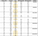
So I made the following table as my translation proposal of @CR0SSBL4DE schematics.
I checked the values with the calculator (on the exception of band 7).

How accurate are the resistors and capacitors ID numbers in the case of a GE7 mod (not the prismatic) ?

Be careful this is table is based on my comprehension and may not be OK 😅
 

Attachments

  • IMG_0822.png
    IMG_0822.png
    155 KB · Views: 2
Back
Top