michaeleschuler
New member
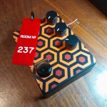
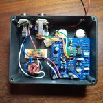
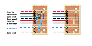
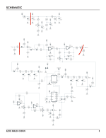
I put together a The Shining-themed pedal enclosure for a friend with the intent of building a simple circuit from scratch to go in it--whatever he wanted. Unfortunately he finally decided on an analog chorus, which is well beyond my scratch-building capacity. So I shoehorned in a Aion Azure (CE-2) board, putting the 3PDT daughter board components on vero to accommodate the DPDT key switch. Two pots are also relocated to accommodate the existing enclosure design. (I understanding the wire routing may be suboptimal.)
When I powered it up, I got no signal with the switch engaged. When I traced the DC voltages nothing looked obviously wrong. I also checked continuity between off-board components and everything seems OK there.
When I trace the circuit with an audio probe, I get an audio signal through the pedal when it is off. However, when the switch is engaged, I get no audio signal at all--even when I have the probe on the tip of the audio-in cable (completely bypassing the pedal circuit). The only think I can think of is that the switch is connecting to ground and shunting the audio signal from the input jack. But if I check continuity between the tip and ground with the pedal completely disconnected, I don't find any connections.
Does anyone have any thoughts?

When I powered it up, I got no signal with the switch engaged. When I traced the DC voltages nothing looked obviously wrong. I also checked continuity between off-board components and everything seems OK there.
When I trace the circuit with an audio probe, I get an audio signal through the pedal when it is off. However, when the switch is engaged, I get no audio signal at all--even when I have the probe on the tip of the audio-in cable (completely bypassing the pedal circuit). The only think I can think of is that the switch is connecting to ground and shunting the audio signal from the input jack. But if I check continuity between the tip and ground with the pedal completely disconnected, I don't find any connections.
Does anyone have any thoughts?