Nice. Couple of things stand out to me
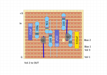
Transistors come in difference pinouts, and I don’t see a note about which transistor you’re using to be able to check those pins are connected right.
You should be able to modify the pin spacing of the transistors in the software to line up with the holes and not have to use those jumpers, which would make it easier to read.
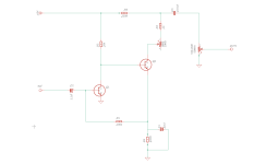
If used as a standalone pedal, you will experience some extreme popping when switching. Need to use a pull-down resistor from input to Gnd. 1M is common. Although, when using electrolytic cap for input, there is a chance you will still get pop as electrolytic can leak DC. If you can experiment and see if a lower value like 1uF doesn’t cut any bass, you could use a 1uF film instead. Tantalum is also an option