Switching for Pickup Simulator Pedal

Song Naga

Member
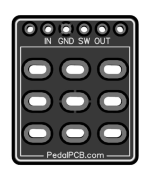
Hi all, I'm working on a pickup simulator pedal based on this article. I've used KiCAD for a few years for little DIY projects and some fairly simple audio electronics projects, but this is my first time dealing with a footswitch and offboard wiring in general. I've successfully built many pedals from PedalPCB but always used these things for the switches and never paid them any more mind than that:

1755878733509.png

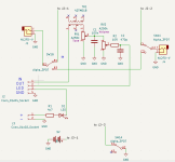
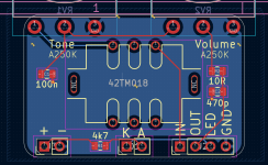
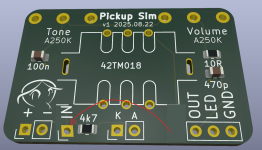
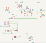
I don't think this PCB for the footswitch will work for my design, since one of the poles is for controlling the LED on/off and the other 2 poles are used for bypass. Hopefully I have things set up correctly so I can wire up the 3PDT footswitch to work as expected. Here's my current schematic and layout, does the offboard wiring stuff look correct? Is there a better/smarter way to do offboard stuff in KiCAD? Thanks for any input!

1755906405167.png


1755905130605.png

1755906443351.png
 
Last edited:
It is good practice to separate IN and OUT. Maybe not that much as on my example, but in-led-gnd-out should be enough.

1755919182420.png

Why such thin tracks? Why ground pour only on the bottom?
 
Last edited:
It is good practice to separate IN and OUT. Maybe not that much as on my example, but in-led-gnd-out should be enough.

View attachment 101757

Why such thin tracks? Why ground pour only on the bottom?
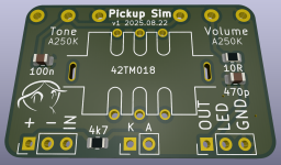
Clever placement of the input pad! I've moved the IN pad per your suggestion.

The tracks were the default thickness for KiCAD, I haven't played enough with net classes to remember to change this at the outset of a project, but this one is simple enough to easily update. I've got 0.5mm traces on the board now:

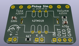
Why ground pour on the bottom only? Habit I guess! I added a top ground pour to see what it would do, and like the result enough to keep it.

Thanks for the ideas and input! Here's the updated board:

1755932428306.png
 
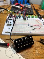
Have you breadboarded the simulator, and if so what did you think of the results? I tinkered with it some and frankly wasn’t super impressed with it. I saw much better results by using a whole humbucker i had laying around in place of the transformer 😂

I have been meaning to get around to just building a 2nd order active low pass filter with resonance instead which should achieve roughly the same thing but haven’t had time.

By the way i like the artwork in the lower left corner of the board, looks cool!
Haven't breadboarded it, I figured it was just as easy to throw it onto a little PCB. We'll see if it winds up on the pile of PCB's that didn't work out. That's just how I tend to design things these days (breadboarding would be much faster).

I'm sure a humbucker would also do the job, but I don't have any on hand to try...

Curious about the 2nd order LPF. I come from synth world and have built many many MANY Eurorack filters. My understanding of the pickup simulator is to allow for response from fuzz pedals similar to how it interacts with non-active pickups. My main guitar uses active pickups so I want something for it, and with the amp sim you can put the fuzz pedal anywhere in the signal chain rather than it having to be the first thing in the chain so it can be directly connected to the passive pickup. I'm not sure how a LPF would achieve this, but I certainly am curious if you have any thoughts.
 
@MichaelW has built a pickup-sim pedal somewhat recently, perhaps he has some advice.


I've got a spare transformer that is an anomaly (can't find anything about it) so may see if it works in this application. Nonetheless, Acuevo's post caused me to ask a group of guitar fiends if anyone has a spare HB that they'd NEVER use in another guitar project. I wouldn't want to deprive anyone the opportunity to have a decent humbucker in their project build/repair/whatever, but I'd like to try a humbucker in a buffer-buster type circuit.


As for the tone control... I'd check out Mark Hammer's Stupidly Wonderful Tone Control, of which Orman (Muzique.com) has a couple of good twists on it.

In fact, I suggest you DO breadboard the circuit just to try out a variety of tone-control ideas.
 
Is it just me or in the schematic above C1 cap should be in series with the Tone pot across the ground to work like the one in the guitars? Now those are in parallel, I think the tone pot will work like a volume pot.
 
Haven't breadboarded it, I figured it was just as easy to throw it onto a little PCB. We'll see if it winds up on the pile of PCB's that didn't work out. That's just how I tend to design things these days (breadboarding would be much faster).

I'm sure a humbucker would also do the job, but I don't have any on hand to try...

Curious about the 2nd order LPF. I come from synth world and have built many many MANY Eurorack filters. My understanding of the pickup simulator is to allow for response from fuzz pedals similar to how it interacts with non-active pickups. My main guitar uses active pickups so I want something for it, and with the amp sim you can put the fuzz pedal anywhere in the signal chain rather than it having to be the first thing in the chain so it can be directly connected to the passive pickup. I'm not sure how a LPF would achieve this, but I certainly am curious if you have any thoughts.
Ahhhh yes for going in front of a low impedance fuzz i think it would be fine. An active LPF definitely would not help with that. My approach was similar but for different reasons - I have an active guitar that i’d like to more closely match to my passive guitars (its overkill in output and brightness, but i can’t bring myself to frankenstein a 3500 dollar guitar into passiveness lol)

it seemed to me that the transformer version didn’t tonally make a whole lot of difference in sounding like different pickups - but i’ve been tinkering with a fuzz face circuit which included an input buffer followed by the transformer and i can tell you that definitely made a difference in how it reacted
 
@MichaelW has built a pickup-sim pedal somewhat recently, perhaps he has some advice.


I've got a spare transformer that is an anomaly (can't find anything about it) so may see if it works in this application. Nonetheless, Acuevo's post caused me to ask a group of guitar fiends if anyone has a spare HB that they'd NEVER use in another guitar project. I wouldn't want to deprive anyone the opportunity to have a decent humbucker in their project build/repair/whatever, but I'd like to try a humbucker in a buffer-buster type circuit.


As for the tone control... I'd check out Mark Hammer's Stupidly Wonderful Tone Control, of which Orman (Muzique.com) has a couple of good twists on it.

In fact, I suggest you DO breadboard the circuit just to try out a variety of tone-control ideas.
The pickup worked well for what i wanted to achieve but the downside was the tonality really wasn’t very adjustable since the pickup measured 16k ohms or so and was stuck there. With the transformer being only 600ish ohms you can stick the series pot afterword and in theory simulate a wide range of pickups but in my experiments i never really achieved this.

I assume it would absolutely achieve the same thing when wanting the same reactivity with a low impedance fuzz it would just be regulated to the sound of whatever pickup you use. It was a fun experiment though!!
 

Attachments

  • IMG_1877.jpeg
    IMG_1877.jpeg
    632.1 KB · Views: 5
Is it just me or in the schematic above C1 cap should be in series with the Tone pot across the ground to work like the one in the guitars? Now those are in parallel, I think the tone pot will work like a volume pot.
It's not you, OP's schematic is not correct to the AMZ schematic. This is why IMHO breadboarding should be necessary, not optional - these sort of mistakes reveal themselves before one commits to a faulty PCB (we've probably all done it)...
 
Quick 'n' dirty Photoshop to bring the tone control in line with the AMZ schemo. (I've made an assumption that that terminal 1 of the pots represents the "clockwise" one, there being no agreement or consensus on that particular subject generally.) I make no warranty, implied or otherwise, about anything else in the image (nor the original query regarding switching) other than the connections between the tone pot and cap and their nearest neighbours:

1755906405167_C copy.png
 
i’ve been tinkering with a fuzz face circuit which included an input buffer followed by the transformer and i can tell you that definitely made a difference in how it reacted
Yeah I really like the idea of putting the pickup sim right into the pedal with the fuzz circuit, I'll definitely explore that and I'm sure both circuits would easily fit in a 125B enclosure if not a smaller one.

Thank you for the updated schematic with the tone control tweak. I'll breadboard it up and trial it along with the original and see what sounds better.
 
Back
Top