Song Naga
Member
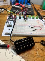
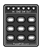
Hi all, I'm working on a pickup simulator pedal based on this article. I've used KiCAD for a few years for little DIY projects and some fairly simple audio electronics projects, but this is my first time dealing with a footswitch and offboard wiring in general. I've successfully built many pedals from PedalPCB but always used these things for the switches and never paid them any more mind than that:

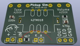
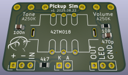
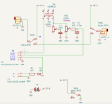
I don't think this PCB for the footswitch will work for my design, since one of the poles is for controlling the LED on/off and the other 2 poles are used for bypass. Hopefully I have things set up correctly so I can wire up the 3PDT footswitch to work as expected. Here's my current schematic and layout, does the offboard wiring stuff look correct? Is there a better/smarter way to do offboard stuff in KiCAD? Thanks for any input!


I don't think this PCB for the footswitch will work for my design, since one of the poles is for controlling the LED on/off and the other 2 poles are used for bypass. Hopefully I have things set up correctly so I can wire up the 3PDT footswitch to work as expected. Here's my current schematic and layout, does the offboard wiring stuff look correct? Is there a better/smarter way to do offboard stuff in KiCAD? Thanks for any input!
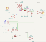
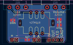
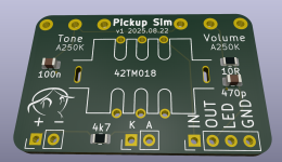
Last edited:

