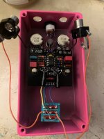
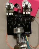
I'm a little embarrassed to ask for help because this is such a simple build and I haven't had such basic trouble in a long while.
Essentially, the pedal does not overdrive. LED turns on and the volume and tone knobs work, but the drive knob does almost nothing. From min to max, the drive knob increases the level by about 3db but there is no clipping. I'm using the Philips OA9 Ge diodes suggested by @MichaelW but also tried a few other types with no difference. The carbon comp resistors are new Arcols (not NOS).
Double checked part values, all seem correct. I tested all the diodes before installing. Everything seems to be oriented correctly. Solder joints all look fine but I reflowed most of them for good measure. Tried a different JRC4558D, same result. I checked continuity of the visible traces on the board, all good. Would love to check all continuity but there is no build doc/no schematic.
I'm hoping someone spots something obvious I missed. Or if there are "usual suspects" for this result (no gain from a gain pedal) please let me know.


new
Essentially, the pedal does not overdrive. LED turns on and the volume and tone knobs work, but the drive knob does almost nothing. From min to max, the drive knob increases the level by about 3db but there is no clipping. I'm using the Philips OA9 Ge diodes suggested by @MichaelW but also tried a few other types with no difference. The carbon comp resistors are new Arcols (not NOS).
Double checked part values, all seem correct. I tested all the diodes before installing. Everything seems to be oriented correctly. Solder joints all look fine but I reflowed most of them for good measure. Tried a different JRC4558D, same result. I checked continuity of the visible traces on the board, all good. Would love to check all continuity but there is no build doc/no schematic.
I'm hoping someone spots something obvious I missed. Or if there are "usual suspects" for this result (no gain from a gain pedal) please let me know.


new
Last edited:

