This Week on the Breadboard: Shallow Water

Should not be noisy. There could be many causes and this is not a troubleshooting thread. ;)

In other news, I tried adding feedback around the BBD like we would find in a flanger. Very interesting. It magnifies the vibrato effect and with a lot of feedback, we get that "talking thru a vacuum cleaner hose" tone. Right now I have the feedback is controlled by a knob, butt-eye think a 3-way toggle switch will do: No Feedback, Moderate Feedback, Heavy Feedback.
 
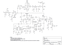
I don't get why Fairfield adds gain in the first stage and then takes it all away in the BBD's input filter. I also don't understand why Fairfield runs the V3207D & CD4046 on 5V when they work as well or better on 9V. Definitely more headroom in the BBD at 9V. The input and output preamps work perfectly well, but could have been implemented by a dual opamp. There is a significant volume shift when turning the MIX knob from Dry to Wet. Not sure why Fairfield did that.

Cool work, just on this note - it would be easy enough to ask him and find out. Guillaume is a mellow guy, he's shared schematics and is pretty open about their stuff.
 
I’m slowly putting the schematic together to build a board. Should I go 1590BB size or try to go stacked 125B? Personally, I’m aiming for stacked 125B, but I’ve never done that before. Thoughts?
 
I’m slowly putting the schematic together to build a board. Should I go 1590BB size or try to go stacked 125B? Personally, I’m aiming for stacked 125B, but I’ve never done that before. Thoughts?
I built this soon after Robert made it available and I plan to explore the Boneyard tweaks. The larger build will give you more room to play around with mods, but if real estate on your board is at a premium, the stacked build would be a better choice.
 
I also don't understand why Fairfield runs the V3207D & CD4046 on 5V when they work as well or better on 9V.
Probably because these parts along with the TINY comprise a digital section on a separate digital supply for noise decoupling. The TINY was the bottleneck for the rail. I'm curious about your other questions, but can't really answer without seeing a schematic of the original circuit. No schematic in the build document. Where are builders getting their randomizer code from?
 
The V3207D is a "mixed mode" part in my mind. The delay line is pure analog. The clocking could be considered digital. The CD4046 is also part analog, part digital.

https://docs.pedalpcb.com/project/LowTide-Schematic-PedalPCB.pdf

If you buy the Low Tide board, a randomizer chip is included. It is similar to the randomizer in the Shallow Water.
The outputs of BBDs are mosfet source followers that are out of phase and only 'on' with different half cycles of the clock. So the outputs look like high frequency pulses that correlate with the clock. It's only after summing and the reconstruction filter that they start to resemble an analog signal again. The BBD also generates noise that correlates with the digital clock. It is good to think of it as a digital device, at least for purposes of decoupling I think.

And yeah, I purchased a kit a few days ago, and also managed to find the schematic. I wasn't sure if the randomizer IC was included.
 
As tempted as I am to build your version I am doing the original low tide to make it more straightforward all on a pcb. But I am trying to implement a few of your mods/recommended improvements without completely overhauling the board. If you or anyone else could assist me I'd appreciate it. I am trying to plan mods ahead of time before I build it.

I don't get why Fairfield adds gain in the first stage and then takes it all away in the BBD's input filter. I also don't understand why Fairfield runs the V3207D & CD4046 on 5V when they work as well or better on 9V. Definitely more headroom in the BBD at 9V. The input and output preamps work perfectly well, but could have been implemented by a dual opamp. There is a significant volume shift when turning the MIX knob from Dry to Wet. Not sure why Fairfield did that.

One of them is powering the cd4046be at 9v instead of 5v. Would it be worth it? Am I correct that I can just
Step1: pull pin 14 and pin 16 of the cd4046be out of the socket
Step2: change c27 to 390 like on yours
Step3: connect them to the vcc

The other is powering the v3207 by 9 volts. It seem's like I can just lift one side of r34 and connect it to 9v with no other changes needed. is that correct? I suppose I might as well swap r11 to 15k like you did as well while I'm there.

I suppose both of these are partially contingent whether the original power filtering circuit is sufficient or if I would need to change that too much as well to be worth doing these 2 mods.

I ended up swapping R32 & R33 to be able to obtain the full adjustment range. What they don't mention is that if you turn the LPG Trim far enough CCW, the filter turns completely off. I do not recommend doing that because it may pop when the filter turns on and off.

Did you mean a straight swap as in trading one for the other? Or did you have to find new values for each? Seems like swapping them might be a good start anyway even it wasn't.


I am really tempted to add the feedback/neutron feature as well! Seems like I should be able to tap in just like you did on the original pretty much. I'll just have to see if can make it fit. Maybe I throw it on a footswitch and add a switch with a couple selectable values? Well no way I can have a decent spot for a footswitch but I can squeeze a jack in there probably to have an ext footswitch.
 
Did you mean a straight swap as in trading one for the other? Or did you have to find new values for each? Seems like swapping them might be a good start anyway even it wasn't.
I meant straight swap, one for the other.

I am really tempted to add the feedback/neutron feature as well! Seems like I should be able to tap in just like you did on the original pretty much. I'll just have to see if can make it fit. Maybe I throw it on a footswitch and add a switch with a couple selectable values? Well no way I can have a decent spot for a footswitch but I can squeeze a jack in there probably to have an ext footswitch.
It's not for everybody and most of the time, I have it turned off. But if you're looking for a totally different tone, then give it a try!
I changed R16 to 22K.
 
しばらくご無沙汰していましたが、質問させてください。
LFO回路(ランダマイザー、MCP602)をElectric Druid TAPLFOに交換することは可能でしょうか?
TAPLFOの出力をフィルタリングしてCD4046に接続すれば可能だと思うのですが、これは実現可能でしょうか?
 
Dunno if that needed reporting, but the translation would be:

It’s been a while, but let me ask you a question.
Is it possible to replace the LFO circuit (Randamizer, MCP602) with the Electric Druid TAPLFO?
I think that it is possible if you filter the output of TAPLFO and connect it to CD4046, but is this feasible?
 
The answer to H.Hik's question is a qualified yes, because we don't get quite the same random waveform from the STOMPLFO. The STOMPLFO generates two random waveforms. The Random Step waveform changes the output to a random voltage at fixed time intervals. Those time intervals are at a constant freq, determined by the voltage at the FREQ pin. The Random Slope waveform ramps the output voltage at a random slope at fixed time intervals. As Robert explained it to me, the Shallow Water's Randomizer steps the output voltage to a random voltage, but not at regular intervals. At each LFO cycle, the Randomizer makes a random decision whether or not to change the output voltage.

when I say "random" here, the waveforms are not truly random because the microcontroller uses a psuedo-random generator to make decisions. A psuedo-random generator produces a very long binary sequence that over short intervals appears to be random, but is actually a fixed sequence. If we reset the generator to zero, it always generates the same long sequence. A 32-bit psuedo-random generator makes a sequence that is almost 4.3 billion steps long before it repeats. Close enough to random for our purposes.

One more thing, the output from the STOMPLFO and Randomizer chips is actually a high-freq pulse code modulated bitstream. It becomes an analog signal when we filter it with a simple R-C filter.
 
Back
Top