This Week on the Breadboard: The Fairfield ~900 Fuzz

Chuck D. Bones

Circuit Wizard
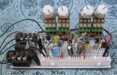
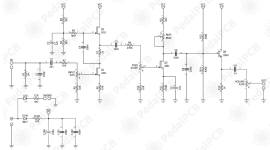
This one has been getting good reviews and demos; here's the breadboard. Built per spec except I subbed BC337-25 for Q4. Q1 & Q3 Idss is around 335μA. Q2 Idss is around 520μA. Q1 & Q2 idle around 330μA. R8 is so low that Q1 runs very close to Idss. Q3 idles around 210μA. The JFET specs given on the schematic indicates Q1 Idss > Q2 Idss which would cause asymmetric clipping in the first stage.

Knobs (L-R): VOLUME - BIAS - FUZZ - INPUT
Fairfield ~900 Fuzz breadboard 02.jpg
 
Last edited:
Pretty nice. I wouldn't call it a Fuzz, more of an OD in my book. Goes from clean to mild distortion to OD. No EQ and it doesn't seem to need it. The BIAS knob doesn't do a whole lot. It's pretty much set and forget. There's one fairly wide sweet spot from . Won't gate.

If anyone has a production pedal, can you measure Q2-S?

I might try it with other JFETs.
 
4.3V is inconclusive.
Let's try that measurement another way. + probe on Q2-S, - probe on the end of R4 that isn't grounded.

With Q2 Idss > Q1 Idss on my breadboard, then with a 3.7Vp-p signal at Q2-S, the waveform is very symmetric with just a touch of 2nd harmonic (about 3%).
If I swap Q1 & Q2 on my breadboard, so that Q1 Idss > Q2 Idss, then the signal at Q2-S becomes visibly less symmetric with the 2nd harmonic up around 5%. Not a big difference.

What we don't know is if Fairfield did this deliberately, or if the JFET matching was close enough that it didn't matter.

I just figured that Q1 & Q2 would clip symmetrically, making mainly odd-order harmonics, and Q3 would be responsible for the even-order harmonics.
 
In other news, I tried various JFETs for Q1 & Q2 in simulation. Most of the ones I tried (MPF4393, J113, 2N5246, 2N5457, 2SK117, BF244A) cut off quite a bit of treble due to their higher Miller capacitance. 2N5484 worked about the same as J201, but required a larger value for R8 (470Ω) to get the biasing in the ballpark. Bottom line, J201 looks like the best choice for Q1 & Q2.
 
If you're looking for another transparent boost, or another JFET OD, then this could be it. I don't envision any other changes. I'm definitely not going to add any knobs.

It would be nice if someone else could chime in on either the original or the mod. After all, I might be full of :poop:.
 
If you're looking for another transparent boost, or another JFET OD, then this could be it. I don't envision any other changes. I'm definitely not going to add any knobs.

It would be nice if someone else could chime in on either the original or the mod. After all, I might be full of :poop:.
Your description of the mod version sounds more in parity with mine built with stock values / components, according to 2.5rev on Fuzzdog pcb

Makes me think that it could have something to do with through-hole J201's vary more than smd mmbfj201 and Fairfield used the latter and so did I.

Doesn't mean there's anything wrong with your mod, I really like that people nowadays make J113 and such work in circuits designed with j201/mmbfj201
 
4.3V is inconclusive.
Let's try that measurement another way. + probe on Q2-S, - probe on the end of R4 that isn't grounded.

I'll have to hunt down the pedal, the voltages are from my notes when tracing. Pretty sure I still have it though.

Yeah right you have a production pedal. You probably just used a pedalpcb schematic.

PedalPCB schematic? Someone is clearly new here.
 
Back
Top