Three Aions in one day!

Your Solstice build and comments in the thread inspired me to come up with a tone/character switch.

Using a Type 1 on-on-on, you could have three values for C16.

Picofarad values (from Tayda's monolithic selection) to play with 100 150 220 270 330 470 560 680 820 1000 — (1000p=stock).

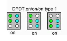
Using 3 caps of your choosing, you'd solder the central switch position cap between lugs 1&6 (type 2 lugs 3 & 4), with the other two caps soldered to 1&4 and 3&6 — signal in to 2 and out from 5 as per normal. At no time are any of the caps in series or parallel with each other.
A-1840.JPG
Actually, the diagram shows a DP3T, if you wanna get technical.

The outer switch-positions’ caps are not in the circuit when bat is in middle; when bat activates 1&4 the centre-diagonal cap is not in the mix because 5&6 are unconnected, and vice versa for cap on 3&6 where the 1&4 and diagonal are not recognised — so 3 separate Values can be attained and placed in order of preference — what I like about this as opposed to doing the same with on-off-on and caps in parallel is that you don't have to have the smallest value in the middle position — it can be a logical low-to-high or high-to-low.

So…
 what'll it be?
100p, 560, 1n OR
100p, 470p, 820p OR

220p, 680p, 1n OR

150p, 330p, 680p OR
⁉️

— OF COURSE ONE COULD JUST BREADBOARD/SOCKET IT AND FIND A PREFERRED OVERALL VALUE, if the differences are too subtle.


Now extrapolate and use this method on an input cap, or other significant signal shaper in a circuit... Maybe the tone cap in a Rat or 808.
Use a 4PDT 4P3T on-on-on (essentially two DP3Ts) on a Muff Tone control...
I had this idea last week because of this mid-high-low problem, but the way I solved it was so much worse. my idea had it go series one way and parallel the other. I drew up this crude diagram to show someone and now I'm a bit embarrassed I came up with such a complicated solution when your simple elegant one existed.


1663198097173.png
 
I had this idea last week because of this mid-high-low problem, but the way I solved it was so much worse. my idea had it go series one way and parallel the other. I drew up this crude diagram to show someone and now I'm a bit embarrassed I came up with such a complicated solution when your simple elegant one existed.


View attachment 32269
Is this loss?

| ||
|| |_
 
I had this idea last week because of this mid-high-low problem, but the way I solved it was so much worse. my idea had it go series one way and parallel the other. I drew up this crude diagram to show someone and now I'm a bit embarrassed I came up with such a complicated solution when your simple elegant one existed.


View attachment 32269

The simple elegant design existed long before I found it. I think after playing around with on-on-on (read "obsessing") about these switches, a little light finally came on in my head and gave me an epic fanny, uhm epiphany. I'm sure the old solder-hands are thinking "yeah, of course it works that way..."


My obsession started with a project that was supposed to be on-on-on but was released as on-off-on; after the PCB supplier corrected the fault, I then found out none of MY on-on-on switches worked in the circuit 'cause they were all type one on-on-on and I needed type 2 on-on-on — which none of my usual switch suppliers carried. After searching high and low for a definitive type 2 (having bought several that were advertised as type 2 but were in fact type 1, still)... Tired. Have had maybe 4 hours sleep total in the last 48... rambling again. On again off again... reminds me of a joke.

Yeah, so, I think I"m beginning to finally get how these damned on-on-on switches work, well at least in one application.
 
Last edited:
Back
Top