SUCCESS! I reflowed lug 2 of the gain pot and that fixed the signal there. You were right about the volume pot, it was f-cked. I switched it out twice before I got one that worked properly (I guess the potentiometer kits from amazon are a crapshoot), and viola, sound emerges!
Some lessons I've learned from this experience that weren't obvious to me:
1. Lugs 1 and 2 of pots should be the same. It makes sense now, but I hadn't specifically read that anywhere. Maybe it's obvious to most people. Oops.
2. Soldering is EVEN more likely to be the problem than I previously believed. It says it in every troubleshooting guide, but I really felt like I'd gotten it down. Some of my pot lug wires were sorta splayed out within the joint, which also wasn't keeping a good connection.
3. How to create and use an audio probe. Holy crap this one is huge. Absolutely could not have done this without that. Invaluable, thank you.
Things I'd like to understand better in the future:
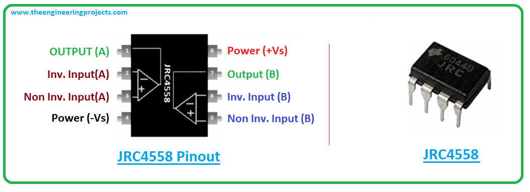
1. How to know what values each pin of the IC should have. I understand that there's a lot to learn about how these work, and so far everything I've read or watched has gone over my head really quickly. But how do people on here use the voltage values of each pin to determine whether or not the IC is working properly? And the same for transistors? Is this just one of those things that takes years to even begin to understand?
2.
Thanks so much for all the help, BuddytheReow. Seriously, I was getting close to thinking it just wasn't gonna be possible for me to continue doing this as a hobby.