fabian1985
New member
Hi everyone,
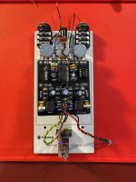
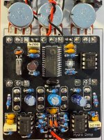
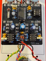
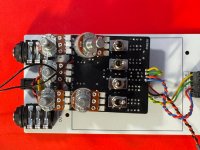
I’m currently troubleshooting my Hydra Delay build using the Auditorium and could really use a second pair of eyes/ears/brain hemispheres.
The dry signal is 100% clean and pristine. However, the wet signal is a brutal, stuttering, bitcrushed noise/distortion. The important detail: The noise reacts to my guitar playing (it's not just random white noise).
I think I've gone through a rigorous debugging process with my multimeter and audio probe to rule out the usual suspects:
Thanks in advance for your help!
Fabian
I’m currently troubleshooting my Hydra Delay build using the Auditorium and could really use a second pair of eyes/ears/brain hemispheres.
The dry signal is 100% clean and pristine. However, the wet signal is a brutal, stuttering, bitcrushed noise/distortion. The important detail: The noise reacts to my guitar playing (it's not just random white noise).
I think I've gone through a rigorous debugging process with my multimeter and audio probe to rule out the usual suspects:
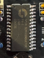
- Audio Probe: The signal is perfectly clean at the input buffer (IC1.1) and stays 100% clean right up to Pin 1 of the FV-1. The glitching noise originates directly inside the DSP and comes out of Pin 28.
- EEPROM Check: When I remove the EEPROM (IC2) from its socket, the wet signal dies completely. So the FV-1 is not booting its internal programs and is at least trying to read the external memory.
- Power & Voltages:
The 3.3V regulator (IC4) outputs exactly 3.32V.
The analog op-amps (IC1 & IC5) have a perfect VREF of 4.40V. No analog clipping at all.
The FV-1 has a perfect DC offset of 1.66V at Pin 28. - Controls:
CTRL1 (Speed) and CTRL2 (Age) provide a perfectly smooth sweep from 0V to 3.32V at Pins 20 and 21 of the FV-1. The Swell/Repeats sits cleanly at the FV-1's Pin 2 at ~1.58V while turning (DC successfully blocked by C17). - Continuity & Solder Joints: I beeped out all connections directly from the SMD pins of the FV-1 to their respective destinations (I2C bus, crystal, audio paths). Everything is connected exactly as per the schematic. Since I have 100% continuity everywhere and also did a reflow on the crystal and C17 pins, I am confident in ruling out cold solder joints.
- The X1 Crystal is dead and - from what I learned - the FV-1 might be falling back to its unstable internal RC clock, causing a massive sample-rate mismatch.
- The EEPROM (IC2) is corrupted an reading a faulty algorithm and outputs digital trash.
Thanks in advance for your help!
Fabian