Trying to mod Expandora with with addon boards

nate433

Active member
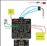
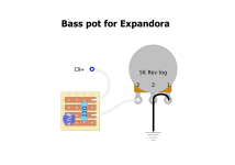
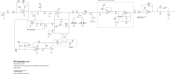
Hey everyone. I'm working on modding an AionFX expandora board by adding the gate and bass contour mod from Chuck Bones as well as an active treble control module after the tone knob. The mods work on my breadboard, but not when i attach them to the PCB. So I'm assuming it's not the addon boards themselves but how i'm connecting them. The contour and gate seem pretty straightforward so I assume I'm doing something wrong with where i'm connecting the active treble mod.

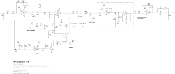
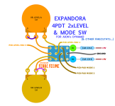
I've attached the schematic with mods surrounded by a dashed box as well as a diagram showing where i'm connecting the mod boards. I'm wondering if i need to lift a leg on C11 or 12 instead of just connecting to them directly to the board. The sound doesn't completely cut out, but gets really quite and sputtery.

Hopefully this is enough info. Figured with diagram would be more clear vs a photo since it's a bit of a rats nest.

Thanks!
 

Attachments

  • expandora mods.png
    expandora mods.png
    316.5 KB · Views: 16
  • hf-expandora-1_5-drive-only.png
    hf-expandora-1_5-drive-only.png
    20.4 KB · Views: 14
  • Expandora bass pot.png
    Expandora bass pot.png
    28.9 KB · Views: 9
  • Active Treble Block.png
    Active Treble Block.png
    105.1 KB · Views: 8
  • 4PDT 2knobjob LEVEL + MODE SW.png
    4PDT 2knobjob LEVEL + MODE SW.png
    184.7 KB · Views: 10
Can't read your schematic, resolution is too poor.


On the Aion schematic, I'd stick C12 on the Active Treble Block daughterboard and use the Aion's C12-pads to insinuate said daughterboard into the circuit. I'd pull the juice for the daughterboard from the Aion board's filtered/protected supply, wherever it's convenient to get it from.


Can't say much more than that because the diagrams provided possibly tell how it ought to be, but not how it is with your physical build —
so, you still need to post pics of the build, spaghetti-be-damned.
 
Here's a higher resolution. It's wired exactly like it's shown in a diagram, double checked to be sure. I'll try to get some photos though if after trying your suggestion doesn't work. So what you're saying is take C12 out and put the 'in' of the treble block on one pad, and the 'out' on the other?
 

Attachments

  • hf-expandora-1_5-drive-only.png
    hf-expandora-1_5-drive-only.png
    162.1 KB · Views: 7
So my dumb ass already did this and didn't realize. I did add c12 to the treble module and have an old note saying to connect it there. I guess that's what i get for coming back to this months later after not working on it 🤦‍♂️
 
Can't read your schematic, resolution is too poor.


On the Aion schematic, I'd stick C12 on the Active Treble Block daughterboard and use the Aion's C12-pads to insinuate said daughterboard into the circuit. I'd pull the juice for the daughterboard from the Aion board's filtered/protected supply, wherever it's convenient to get it from.


Can't say much more than that because the diagrams provided possibly tell how it ought to be, but not how it is with your physical build —
so, you still need to post pics of the build, spaghetti-be-damned.
Only issue now i when i click the mode footswitch i get a pretty significant pop. So just need to figure that out now. I know the common way to fix popping in a bypass switch, but will have to see if any of them work in this case. This one feels like it might be the most likely issue:

I appreciate you looking at this and also providing me with the wiring for the foot switch a while back!
 
Last edited:
Can relate to being a months-later dumb-ass. I've got breadboards that I didn't bother labelling, in the heat of battle "well it's obviously this abc-circuit and I'll work on it tomorrow" and then came back to it months later wondering what the hell it is and what was I doing with it and then have to trace it all out and see what substitutions I've made to it etc... All that is a total PITA to rethink/retrace/remap/etc and so the project gets pushed aside and I'm loathe to pull apart the breadboard lest I miss a key mod I've made...

With actual PCB builds, it's even worse.
Year(s)-old abandoned projects await trouble-shooting.


Anyhooo...

The popping...


Popping source could be from


  • energy stored up in C13/C14, since the pot-swap is on a couple of gain-controls for OA-3.2, instead of where you'd swap out two typical VOL controls with each pot's leg-1 going to ground.

  • energy stored in C6 and or the pop reaching the H11F33

  • or as you mentioned the mode indication-LED.


So... easy to check if it's the LED, delete it and test for popping.

If it's either of the other two, or both, then a PDR might help. If it's something to do with the vactrol... 🤷‍♂️


Please bear in mind, I'm just shooting into the dark with blanks. 😸
I can't seem to trouble-shoot my own builds, so probably shouldn't be trying to guesstimate what's going on in other DIYer's projects.
 
Back
Top