PedalBuilder
Well-known member
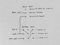
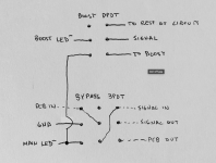
I've been playing around with a circuit (Spaceman Sputnik) that has two footswitches: one for engaging/bypassing the effect and the second for engaging a feedback loop feature. I would like to have the LED for the feedback loop turn off when the effect is bypassed and the feedback loop is still engaged. I think I've found a solution, but I'd appreciate any feedback/confirmation that you all might have.
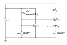
Here's the schematic:

The basic idea is that the LED pole of the bypass/engage footswitch is setup so that when the effect is bypassed, the LED pole is connected to ground. Conversely, when the feedback loop (it's labeled boost in the schematic above, but what's in a name?) is engaged, the LED pole open and not connected to anything.
When the effect is engaged, there is a positive voltage at the gate of Q1 that turns it on and connects the bypass indicator LED's cathode to ground, thereby turning on the LED. The same voltage that turns on Q1 is also applied to the gate of Q2, turning it on and connecting the anode of the feedback loop indicator to its current limiting resistor. Switching on/off the feedback loop footswitch connects/disconnects the cathode of the feedback loop indicator LED to ground, turning it on/off.
When the effect is bypassed, the gates of Q1 and Q2 are connected to ground, turning them both off and turning off both LEDs (disconnecting D1 from ground and disconnecting D2 from its current source). Power is then connected to ground through the 10M resistor, which should result in a negligible current consumption of 900 nA when the effect is bypassed.
I don't have any MOSFETs on hand to test this on a breadboard, but it worked fine in CircuitLab, so hopefully that means that it will work in the real world, too. That said, I'd appreciate any feedback that you all might have!
Here's the schematic:

The basic idea is that the LED pole of the bypass/engage footswitch is setup so that when the effect is bypassed, the LED pole is connected to ground. Conversely, when the feedback loop (it's labeled boost in the schematic above, but what's in a name?) is engaged, the LED pole open and not connected to anything.
When the effect is engaged, there is a positive voltage at the gate of Q1 that turns it on and connects the bypass indicator LED's cathode to ground, thereby turning on the LED. The same voltage that turns on Q1 is also applied to the gate of Q2, turning it on and connecting the anode of the feedback loop indicator to its current limiting resistor. Switching on/off the feedback loop footswitch connects/disconnects the cathode of the feedback loop indicator LED to ground, turning it on/off.
When the effect is bypassed, the gates of Q1 and Q2 are connected to ground, turning them both off and turning off both LEDs (disconnecting D1 from ground and disconnecting D2 from its current source). Power is then connected to ground through the 10M resistor, which should result in a negligible current consumption of 900 nA when the effect is bypassed.
I don't have any MOSFETs on hand to test this on a breadboard, but it worked fine in CircuitLab, so hopefully that means that it will work in the real world, too. That said, I'd appreciate any feedback that you all might have!


