Twin Face PNP problem

pejotlq

New member
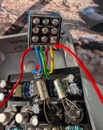
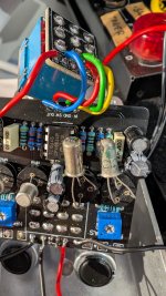
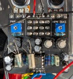
I'm having a problem with PNP bias in Twinface: https://www.pedalpcb.com/product/twinface/

In PNP mode, the voltage between transistor Q2's collector and ground is regulated between -7.19 and -8.72, and I can't set the recommended -4.5.
The NPN is working correctly.
In NPN mode, transistor PNP2 should have a constant -9V, but in my case, by adjusting the trimmer, it can be adjusted between -8.88 and -8.93V.
R1, soldered in, showed around 15kO, and after desoldering, it showed the correct value of 33kO - does that matter?
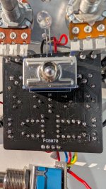
I checked the transistors with a diode test. The switch was checked with a continuity test.
All components are polarized in the correct direction.

Can you help me?
 

Attachments

  • PXL_20250823_211422208.jpg
    PXL_20250823_211422208.jpg
    597.1 KB · Views: 10
  • PXL_20250823_201830237.jpg
    PXL_20250823_201830237.jpg
    451 KB · Views: 13
  • PXL_20250823_201758746.jpg
    PXL_20250823_201758746.jpg
    720.1 KB · Views: 13
  • PXL_20250823_201701658.jpg
    PXL_20250823_201701658.jpg
    469.7 KB · Views: 12
Howdy!
I have been breadboarding this circuit in preparation for committing to the PCB and had a similar problem. What I have learned is that, for lower gain Germanium transistors, it's necessary to adjust R4 (100k in the build guide) to get the voltage down to lower levels. A significantly lower resistance at R4 will shift the bias. Using a 100k trimpot, at this location, I found that for my Ge a resistor of around 68k is what I need to get the Q2 collector to -4.5V.
If you have the ability to work a trim pot into this point, or can build the PNP circuit on a breadboard, I found that I can dial in the R4 and the PNP bias trimpots to get exactly the reference voltages for the PNP circuit (I refer to Electro Smash's Fuzz Face Analysis for nominal targets around the circuit - I can hit -4.5 V, -0.7 V, and -0.2 V where indicated). Having found the sweet spot for my two transistors on the bread board, I am going to go with the closest fixed resistor match to what worked for me on the breadboard. This does lead to a circuit that performs pretty well - at high fuzz the circuit starts to fuzz smoothly from a guitar volume of 5, to heavy fuzz at 10 (single coil on a strat), and at lower fuzz the volume just has to move higher, but the tone is also different.
 
R1, soldered in, showed around 15kO, and after desoldering, it showed the correct value of 33kO - does that matter?
you won't get a reliable resistor reading if the resistor is in circuit, so this is expected.

regarding biasing the PNP side, can you try swapping the transistors to see if you get different results. Do you know the specs of those?
 
I tried using different resistors as suggested above, but another problem arose. Or maybe it's not the problem...
I'm reading the collector voltage, but instead of showing a constant value, e.g., -6, the voltage decreases, e.g., 6 5.90 5.8 5.7 5.6 5.7 5.6 5.5 ...
I don't have the specifications for the AC128 transistors.
What's the problem?
 
Back
Top