Understanding the Cornish style buffer (C-Buffer)

I guess the first question would be - have you built the stock circuit (or one of the modded versions for Chuck D B or Lucifers Trip) and discovered that you DON'T have that consistency?
Fantastic question - no. I really should. I have a tendency to get ahead of myself =P but it is a BJT fuzz with a low input impedance, so I already know it won't react well to having pedals placed before it. I just had questions about buffers and decided to ask them so that I could learn. If I have a question in specific to my ambitions re a redesign, I'll put it in a new thread to avoid toooo much off topic discussion.
 
Gotcha. With regard to the Cornish buffer and input impedance, per your original question, this DIYS thread might be useful to you?

As an aside, one suggestion that's come up from time-to-time on other forums is in lieu of a unity(ish)-gain buffer, to use the Tillman preamp but replace the gate resistor with a 1M pot, and then put a voltage divider after it to help you achieve the amount of tone suck and volume drop that you need for a given application.
 
Gotcha. With regard to the Cornish buffer and input impedance, per your original question, this DIYS thread might be useful to you?
I'll have a look at that now, thanks!
use the Tillman preamp but replace the gate resistor with a 1M pot, and then put a voltage divider after it to help you achieve the amount of tone suck and volume drop that you need for a given application.
Oooh that sounds very promising (and very interesting). I will have to try that out in addition to a clean buffer. Cheers (y)
 
Gotcha. With regard to the Cornish buffer and input impedance, per your original question, this DIYS thread might be useful to you?

As an aside, one suggestion that's come up from time-to-time on other forums is in lieu of a unity(ish)-gain buffer, to use the Tillman preamp but replace the gate resistor with a 1M pot, and then put a voltage divider after it to help you achieve the amount of tone suck and volume drop that you need for a given application.

Semi related to the Tillman Preamp is Gez Pelton's impedance matcher, at the bottom of this page: http://www.home-wrecker.com/wahmods.html
 
As an aside, one suggestion that's come up from time-to-time on other forums is in lieu of a unity(ish)-gain buffer, to use the Tillman preamp but replace the gate resistor with a 1M pot, and then put a voltage divider after it to help you achieve the amount of tone suck and volume drop that you need for a given application.
Sorry to come back to that, but where would I put the voltage divider on the schematic? Is it between R3 (now a 1M pot) and 9V? What value should I use for the extra resistor to make the voltage divider? Sorry if these are dumb questions haha
 
Okay folks.

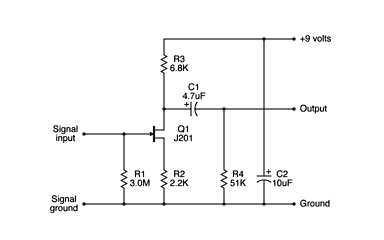
Here is a little calculator I put together:


Shows Common Emitter Amplifier stages with and without bootstrapping resistor and capacitors. Also shows an Emitter Follower with and without the bootstrapping components.

I'm not sure I am accounting for the effect of the bootstrapping resistor correctly in the Emitter Follower, as I simply brought over the same calcs as in the CE Amplifier stage.

My research seemed to indicate that a bootstrapped Emitter Follower was subject to:

Input Impedance = Rbs/(1-Av)

but that seemed to yield ridiculously high input impedance vs. the Bootstrapped Common Emitter stage.

Anyway, pick it apart and maybe we can make something useful out of it.
This is brilliant. Will be using it. 👍
 
Sorry to come back to that, but where would I put the voltage divider on the schematic? Is it between R3 (now a 1M pot) and 9V? What value should I use for the extra resistor to make the voltage divider? Sorry if these are dumb questions haha
Sorry, by "voltage divider" I just meant your typical "volume knob." Per this schem:

preamp.gif


R1 becomes a 1M pot - tie lug 1 to ground, lug 2 to gate.
OUTPUT goes to lug three of a 100K (or whatever) pot, lug 2 to the next stage, lug 3 to ground.

(You can remove R4 if you're adding a pot).
 
Sorry, by "voltage divider" I just meant your typical "volume knob." Per this schem:

preamp.gif


R1 becomes a 1M pot - tie lug 1 to ground, lug 2 to gate.
OUTPUT goes to lug three of a 100K (or whatever) pot, lug 2 to the next stage, lug 3 to ground.

(You can remove R4 if you're adding a pot).
Thank you for explaining. Much appreciated!
 
Also very interesting! Don't MOSFETs have higher noise floors than JFETs at lower frequencies? Would it make sense to build it with a JFET instead? Or is that just CMOS architecture? I think a 9v1 zener should also be placed between the gate and the source as protection.

Don’t quote me on understanding this correctly but I believe you only need the gate protection diode on it if it’s the very first stage in a design, going off of this @Chuck D. Bones comment on a MOSFET AIAB: https://forum.pedalpcb.com/threads/dunwich-da-120-on-a-breadboard.13465/page-2#post-215875 But yeah MOSFETs are definitely noisier than JFETs.

I saw in a different thread elsewhere you mention SMD and some models of the SMD 2n7002 (I believe suffixes A and K? but varies by supplier) have this diode built into it
Thanks for clarifying, that makes sense (y)
 
The principle of a bootstrapped device is actually quite simple to understand.

Cornish buffers are emitter followers, meaning they have a voltage gain close to one. On emitter followers, the signal is taken from the emitter and it is nearly a 1:1 copy of the input. A suitably large capacitor will convey any voltage change on the emitter back to the base, which is why both of them "see" the same voltage. No voltage change means no current change. No current change means infinite resistance.
Note: this is only valid for a signal change, not for static conditions.
What "AC" means in this therm is determined by the size of the bootstrapping capacitor obviously.

Cornish describes a scenario in his case against true bypass that probably will not affect 95% of us guys here.
That said, I am a long time promoter of buffering, but where necessary (and it is necessary in the scenario Cornish describes).

It is true that very many pedals have a too low impedance. Fuzz faces and derivatives are notorious for that, and should and can be fixed.
The purported "sterile tone" is just lack of understanding of the problem.

On the above linked page he writes:
a fiendishly clever pre amp that has the same characteristics as the input of a tube amp (1 Megohm/20pF), a highly efficient filter to eliminate the possibility of radio breakthrough and a low output impedance so that any following pedals/ cables etc. will not impose a load on the guitar signal.

Excuse me, but this is applied a bit thickly for my taste, to put it mildly (probably to highlight its superiority)
Provided he talks about the same circuit as we here,
  1. I do not see what is so extraordinary about it, although its components are certainly chosen with care for low noise and max. headroom.
  2. 1 Mohm is nothing extraordinary. 20pF is not needed, any length of cable will soon have several hundreds of pF.
  3. The highly efficient RF filter is a mere capacitor chosen big enough to roll off all RF frequencies (note that the small cap on the base will cancel out too...)
  4. Low output impedance... any old follower can do that. A few 100 Ohms are plenty low enough.
Although I believe the problem must be paid attention to, two such buffers stacked are way overkill.
The principle is proven working, which is why he uses it.
OP-amps principally work, but with today's flood of OPA's and their touted all-around superiority (and probably programmed obsolescence)
you have no time to gain experience on their overload recovery behavior, their headroom, their clipping mechanism and so on. We do not know how well the input is protected against spikes.

Note that the op-amp follower shown here somewhere will not work in the bare-bone configuration shown. It needs a bias, it has no RF protection etc. Very many schematics available do not provide any such protection.

With all this ado about keeping the signal pristine, one problem I never saw mentioned in this context is that the signal degrades, as soon as it leaves the guitar. Although a bit cumbersome in practise, the signal should be buffered right at the guitar, or tone will be degraded by the time it hits the first input. And this applies regardless of the subsequent device, even if it were a tube amp grid. The cable capacity has done its job.

Edit: The "C"-Buffer or the "K"-Buffer are highly regarded. They sound so good. This is entirely ridiculous. You will never hear any buffer. What you hear is the absence of the gremlins it just saved you from. Somebody even sells a K/C buffer. :rolleyes:
Note that the cherished K-Buffer does not have any RF protection.

While the point Cornish brings up might be debatable, the double buffering appears a total overkill to me. What is not debatable is that many circuits and maybe a Muff too have a too low input impedance and do benefit from a buffered front-end, true bypass or not.

Hope this helps.
 
Last edited:
I just found this here from JHS pedals: Understanding Buffers
If you are using several true-bypass pedals, you will likely experience some tone loss. For this reason, it’s helpful to have a mixture of true-bypass pedals and buffered-bypass pedals on your board.

And this is closer to the truth IMHO.

That said, you may ask yourself: "from when on do I experience tone loss?"
From the moment the signal leaves your guitar. The lower your drive impedance is, the more it can drive without loss becoming apparent. (Note: there is always loss, but you can stop it from becoming apparent too early.)

This brings us back to the point I made earlier: the best insurance is to have a buffer either inside the guitar or immediately after it.

And if somebody claims this ruins your tone - you did not take the time to try to understand the problem. I have been going on at length about this on my web pages, and none of my fellow musicians ever felt my tone were ruined by buffering properly.

Thinking about the double Cornish buffer again... I should have mentioned that I refer to the circuit AIONFX has traced, which eventually peaked in their HALO deluxe kit. This schematic obviously is the result of a BMP pedal Cornish re-worked. Naturally, Pete did not comment his work, so the double buffering very likely has other reasons than achieving a ridiculously high input impedance. Maybe he incorporated a splitter or whatever. We cannot know, but two stacked high impedance buffers just make no sense for preserving signal quality even in the most stringent environments.
 
Last edited:
Back
Top