Understanding the Cornish style buffer (C-Buffer)

mzy12

Active member
Hello!

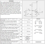
I was watching a video trying to understand how emitter-follower amps work. In relation to the C-Buffer, there are some things I don't understand - I can't find any model for emitter-followers that include C2, C3, R4 and R7. ( I checked this website and this website)

I also wonder about the input impedance - this calculator says that it's around 600k, assuming, generously, that the BC459 is operating constantly at its max hfe of 500. I would have thought that the impedance would ideally be more around 1M. Maybe R4 is influencing the impedance in a way that I don't understand.

Any help would be appreciated, thanks!
 
I think I could figure out answers to your questions, but it would probably take me a really long time and then somebody who actually knows what they're doing would correct me but by then who knows how many times the thread would flip and burn. Sorry for derailing your legit question 🤦🏻‍♂️
 
I think I could figure out answers to your questions, but it would probably take me a really long time and then somebody who actually knows what they're doing would correct me but by then who knows how many times the thread would flip and burn. Sorry for derailing your legit question 🤦🏻‍♂️
Don't worry about it (y) maybe I should ask this one on something like the eevblog forum? Electric instrument electronics are at the interesting cross section of general electrical engineering principle and niche, applied knowledge, often learned from the practical side of things. Sometimes it's hard to know what to ask and how to ask it, but everyone here has been great so far!
 
Hey it’s just bad timing that the other thread is so fresh in everyone’s minds haha.

I can’t necessarily help with the calculations, but I’ve read many places that it’s that its a “Bootstrap” concept. Attached is a snippet from the Wikipedia on “Bootstrapping (electronics)”.

I’ve seen the Cornish buffer listed as 1M impedance, I haven’t personally studied boostrap circuits enough to verify that.
 

Attachments

  • 6EC7C4C3-D9B4-4EE2-A7F2-B411D1775675.jpeg
    6EC7C4C3-D9B4-4EE2-A7F2-B411D1775675.jpeg
    135.3 KB · Views: 12
Don't worry about it (y) maybe I should ask this one on something like the eevblog forum? Electric instrument electronics are at the interesting cross section of general electrical engineering principle and niche, applied knowledge, often learned from the practical side of things. Sometimes it's hard to know what to ask and how to ask it, but everyone here has been great so far!

There is an upper limit on the input impedance with BJTs for both emitter followers and common emitter stages.

Using a Darlington can help to achieve higher input impedance in the common emitter stage but makes no difference in the upper limit of the emitter follower.

I’m not 100% sure how it does it, but it IS in fact the “bootstrapping” that helps raise the upper limit of the input impedance.
Makes sense. I think. I saw this post on the other cornish thread:

Yeah the cornish buffer costs pennies compared to an op amp buffer or even a jfet one. The trade off is obviously board space and the time it takes to assemble more components which both also heave real costs.

I’ve always been kind of impressed with high input impedence BJT designs because of how cheap they are. You could even get much more complicated than cornish’s bootstrapped emitter follower if you wanted, here’s some from Douglas Self:

Design B practically lives on my breadboard but is obviously overkill

View attachment 57939
Honestly design B there kind of looks tempting. At least for the front end of a circuit. I will have to look into more of what this Douglas Self fella wrote about them.
 
If we look at a few calculator examples:

Here is a pretty straightforward Common Emitter Gain stage, setup like the recovery stage from my favorite Ram's Head Big Muff circuit:

1697544079968.png

Here is the exact same setup, but with a bootstrap resistor similar to the one in the cornish buffers:

1697544170389.png

Here is a basic Emitter Follower setup with similar values:

1697544251237.png

Input impedance of the basic Emitter Follower and Common Emitter stages are similar, so I can only imagine the bootstrap resistor does something very similar in the emitter follower.

Frankly, that increase in impedance is staggering. I may incorporate the bootstrapping concept into my integrated Fuzz Buffer.
 

Attachments

  • 1697544231103.png
    1697544231103.png
    123.9 KB · Views: 4
Didn't realise that
If we look at a few calculator examples:

Here is a pretty straightforward Common Emitter Gain stage, setup like the recovery stage from my favorite Ram's Head Big Muff circuit:

View attachment 58583

Here is the exact same setup, but with a bootstrap resistor similar to the one in the cornish buffers:

View attachment 58584

Here is a basic Emitter Follower setup with similar values:

View attachment 58586

Input impedance of the basic Emitter Follower and Common Emitter stages are similar, so I can only imagine the bootstrap resistor does something very similar in the emitter follower.

Frankly, that increase in impedance is staggering. I may incorporate the bootstrapping concept into my integrated Fuzz Buffer.
Didn't realise that there were more calculators on that site. That input impedance and output impedance is impressive on that last one. Personally I don't see any reason not to use it over the single BJT emitter-follower circuit shown on the first calculation I linked (EDIT: misread it and thought there were multiple transistors). What's the current buffer config you use on your Pompeii fuzz? I tried googling to see you talking about it on this site, but google keeps thinking I'm looking for archeological schematics of the actual location of Pompeii :p
To be fair no one was discussing Cornish buffers in that thread (even though the OP meant well), so maybe it's working exactly as it should. :ROFLMAO:
Can't fault that. I think that thread is like the monkeys on the typewriter at this stage - eventually it will write Shakespeare and even start discussing the Cornish buffer again.
 
Last edited:
I'm not sure which schematic you're looking at, but I'm guessing that one of the caps you're referencing is the 1N between B-E? That's there to block RFI.

Personally I don't see any reason not to use it over the single BJT emitter-follower.

My cursory understanding is that with bootstrapping you're sacrificing flat response (which is "ideal" in a buffer), and adding complexity (more parts), to solve a problem that would be better handled by a simple FET or opamp solution. So you're left with a relatively complex, 'imperfect' buffer.

The missing context is maybe, again, that Cornish is designing things based largely on parts/methodology/design principles from the 50s-70s. You're getting a Cornish pedal not because it represents the apex of 21st century small signal amplification design or whatever, but because you want to buy the thing from the guy who's been making it the same way for 40yrs, progress be damned etc.

You might like the way the Cornish buffer design sounds with your guitar or how it reacts with your particular pedal design? If so cool, party onward. If you just need an input buffer for whatever reason there are much simpler ways to go.
 
Didn't realise that

Didn't realise that there were more calculators on that site. That input impedance and output impedance is impressive on that last one. Personally I don't see any reason not to use it over the single BJT emitter-follower. What's the current buffer config you use on your Pompeii fuzz? I tried googling to see you talking about it on this site, but google keeps thinking I'm looking for archeological schematics of the actual location of Pompeii :p

I have not released my circuit. It's nothing special so keeping it a secret is ABSOLUTELY me trying to maintain a competitive advantage. You won;t catch me defending it's what a novel invention it is! :D

Mainly it's a tweaked Darlington CE gain stage. It has a specific output impedance and then some filtering at the output for maintaining dynamics and cleanup.

Right now I'm trying to understand the equations for bootstrap resistors in both CE and CC stages. Then I can put those calcs into my Excel sheet and compare to the Guitar Science calculators.
 
Back
Top