benny_profane
Well-known member
I really enjoy building utility circuits: signal routers, mixers, patch boxes, etc.—anything that can open up different options without changing fundamental elements or introducing anything new.
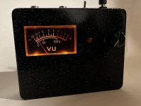
Even though their real utility is debatable and there are many other (better) line monitors, analogue needle VU meters have always been interesting to me. The addition of the peak detection circuit makes this more versatile and helps give a quick visual indication of transient spikes to avoid nasty clipping with my headphone amp.
I found a cheap DC meter on ebay and worked from the schematic in Figure 9 here. The SENSITIVITY control is a panel control; CALIBRATION is a trimmer. The meter didn't have a backlight, so I made a small LED daughterboard, filed out some notches, and secured it to the meter housing. It's set it so that the backlight is on when the circuit is active.
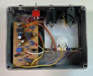
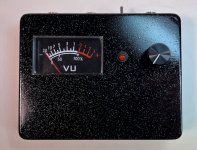
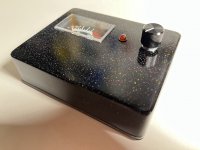
Last edited:

