Wiring strategy for 2 PCB combo pedal

zipfool

Member
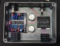
I'm thinking through the layout and wiring strategy for a 2 effect combo pedal that I'm experimenting with. I've just roughed everything into a spare enclosure w/ a bunch of nonsense holes. Still haven't assembled the Squidward board, but it's mocked in there according to scale.

These are the PCBs I want to include:
  • Waddle Box
  • Squidward
I don't foresee using both effects at the same time. Just trying to put everything into one enclosure.
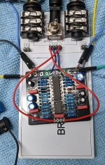
I'm concerned about noise mitigation because some of the wire runs are a lot longer than I usually do. Wondering if anyone has suggestions for routing the wires so the circuit is a quiet as possible. I would imagine some of these would be good to twist together, but I realize maybe that only works in amplifier circuits.

I'm also wondering if I'm in for a world of hurt putting the waddle box pub so close to the input. In the final enclosure, I'll move the input closer to the middle so it doesn't hit the red film box cap. But of course I have to tilt the electro caps downward to get everything to fit.

Thoughts? Suggestions? Prayers?
 

Attachments

  • screenshot_15.jpg
    screenshot_15.jpg
    1.6 MB · Views: 53
I very seriously doubt you will have much of a problem with noise, along as the box is grounded. Signals and voltages in those circuits are small, and consume relatively little current. Interference from outside will be the consideration. Not to say the circuits as designed and built can't be noisy, but wire routing probably will have little effect. That said, wire twisting is quick and easy, and can't hurt..
 
I very seriously doubt you will have much of a problem with noise, along as the box is grounded. Signals and voltages in those circuits are small, and consume relatively little current. Interference from outside will be the consideration. Not to say the circuits as designed and built can't be noisy, but wire routing probably will have little effect. That said, wire twisting is quick and easy, and can't hurt..
This is great advice. You should be fine as those two boards don't have any potentially problematic elements like digital circuits or LFOs.

I haven't really had an issue with interference or noise in 2-in-1 builds, but I do twist signal/power & ground wires for longer runs. If you really want to prevent interference, make sure you run your longer signal wires away from the PCBs, tucked into the corners of your enclosure.
A related question, I'm hoping to use a single LED to indicate which circuit is activated (or both circuits at the same time.) I thought that a tri-color LED like this would do the trick:


The LED has three leads, 2 separate anodes and a common cathode. My thought was to connect the anode terminal from each pcb to a different anode on the LED, and then connect the PCB cathodes to the common cathode on the LED. This way, there's 4 different states for the LED:

1. PCB 1 is active
2. PCB 2 is active
3. Both PCBs are active
4. LED is off - pedal is in full bypass

A few questions:
Will this work?
The description for the LED says that the series resistor is 800ohm. But series resistors for PCBs is 4k7. Is this a problem?
 
from my amp building experience: avoid parallel runs of signal wire in close proximity, avoid running unshielded wire runs across the circuit board, if unshielded signal wire runs have to intersect, make sure they're as close to 90 degrees as possible ...
 
Not sure about the LED. In your OP: I think you have a lot of extra ground wires that might be trouble when you are wiring this up. You only need one ground wire from each PCB and one from the DC jack connected to the enclosure ground at the audio jacks. For good measure you can add a connecting ground wire between the audio jacks if you ended up routing the first 3 grounds to different audio jacks.
 
Not sure about the LED. In your OP: I think you have a lot of extra ground wires that might be trouble when you are wiring this up. You only need one ground wire from each PCB and one from the DC jack connected to the enclosure ground at the audio jacks. For good measure you can add a connecting ground wire between the audio jacks if you ended up routing the first 3 grounds to different audio jacks.
Thanks! Whats the purpose of that wire between the two jacks? Is that in case the jacks' mechanical connection to enclosure isn't solid enough?
 
Pretty much. It's following the star grounding idea, where you have everything grounded to the same point. It's meant to prevent ground loops, but like most things in pedal-land, not something to worry a lot about.
 
A related question, I'm hoping to use a single LED to indicate which circuit is activated (or both circuits at the same time.) I thought that a tri-color LED like this would do the trick:


The LED has three leads, 2 separate anodes and a common cathode. My thought was to connect the anode terminal from each pcb to a different anode on the LED, and then connect the PCB cathodes to the common cathode on the LED. This way, there's 4 different states for the LED:

1. PCB 1 is active
2. PCB 2 is active
3. Both PCBs are active
4. LED is off - pedal is in full bypass

A few questions:
Will this work?
The description for the LED says that the series resistor is 800ohm. But series resistors for PCBs is 4k7. Is this a problem?
Sounds like that would work to me, you may want to test that resistor value with a battery before installing, might be pretty bright
 
Sounds like that would work to me, you may want to test that resistor value with a battery before installing, might be pretty bright
So, looking at the schematics for these PCBs, it looks like the footswitch completes or blocks the LEDs cathode connection to ground.

I realized that, since there are two PCBs and each have their respective footswitch, I should probably use an LED with common anode (not cathode).

Check my logic though:
If I use an RGB LED that has common anode, then I just need to attach the LED anode to one of the PCBs. Then I need to connect each PCB's cathode pad to a different/separate cathode leg on the LED.

Here's the LED I got:

This way, there's three separate colors:
Red = PCB 1 is active
Blue = PCB 2 is active
Magenta = both PCBs are active
 
Pretty much. It's following the star grounding idea, where you have everything grounded to the same point. It's meant to prevent ground loops, but like most things in pedal-land, not something to worry a lot about.
Okay. The reason I ask on is because, unless I'm misunderstanding, there are typically 3 wire that go from a pedalpcb and ground. All 3 are typically on the same side of the board:

1. Ground that goes to input
2. Ground that goes to output
3. (-) or ground that goes to the negative terminal of power jack

Am I misunderstanding something? Or are you saying that only one of the grounds to input/output are necessary for each PCB?
 
Yes, this is mostly true. In rare instances a PCB might have two separated ground pours for isolation and you would need two ground wires to the PCB.
 
Interesting, that reminds me that when I do a test using one of the mini prototyping rigs, I never have to connect anything to/from *either* of those extra ground pads and it all still works. Perhaps they're just there so I can make a more direct ground connection to the jacks (in case the mechanical connection isn't enough.)
 

Attachments

  • PXL_20211011_011130996~2.jpg
    PXL_20211011_011130996~2.jpg
    738.2 KB · Views: 7
So here's the thing. If the enclosure is metal, you only really need to ground the input jack, the output is grounded through said enclosure. I've been doing it that way for 10 years now.
 
@PedalPCB , are there two separate ground paths in these PCBs? If not, us there any harm in only using one gnd pad (per PCB) to connect to the jacks?
You can check for continuity between all of the ground pads to test for this. Most of the time the extra ground pads are there for convenience. For example you can run a ground wire from the DC jack to the enclosure or you can run it to the PCB right next to the power input.
 
Back
Top