SOLVED Wren and cuff your face question

PAGOON

Active member
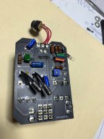
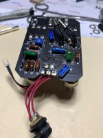
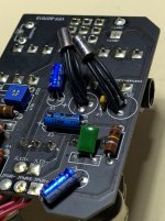
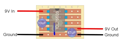
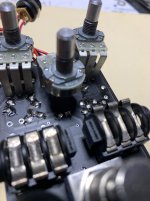
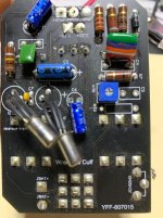
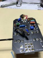
I bought this wren and cuff your face off eBay a long time ago… it says it was from an estate sale… I hate when people say that in a listing anyways I gots it pretty cheap.. it would need a voltage inverter to work I think the transistors are GS109 PNP?Any thoughts on how to wire a voltage inverter in… would I have to cut the trace? The trace runs all the way down the left of the board…my question is where do I install the voltage inverter.Can I cut the trace where I have the screwdriver that would be on the input side…Would I cut it there… or is it simpler to throw some Npn silicon in there and if I do that I’d have to flip the electrolytics correct? I think wren and cuff attaches a separate circuit to these boards I don’t really see any evidence of it being soldered and desoldered…
 

Attachments

  • image.jpg
    image.jpg
    674.4 KB · Views: 11
  • image.jpg
    image.jpg
    632.7 KB · Views: 10
  • image.jpg
    image.jpg
    754.6 KB · Views: 11
  • IMG_6693.webp
    IMG_6693.webp
    13.3 KB · Views: 8
  • image.jpg
    image.jpg
    578.9 KB · Views: 9
  • image.jpg
    image.jpg
    749.5 KB · Views: 8
  • image.jpg
    image.jpg
    588 KB · Views: 9
Are we sure it's not already adapted to a negative ground? Wren and Cuff may have flipped the circuit upside down so it'd run on a standard pedal power supply. The product description says negative tip and I don't see a charge pump in any other pics.

I see the trace leading to JPWR+, which appears to be ground, and thought it was a positive ground layout, but then I see that JPWR+ actually connects to the negative terminal of the DC jack... (Well, technically.... WE call it the negative terminal but the rest of the modern world calls it the positive terminal, so that could explain the ambiguity)

If the DC jack wiring is original it might not need any modifications. If it's not original and the PCB was expecting positive ground, after repairing the damage, you could insert the voltage inverter right there between the DC jack and the PCB.

Ideally, we should trace the PCB and see what we're dealing with before blindly feeding it reverse polarities.


I do see a little stripboard daughterboard in this one, but it looks like it only has two wires so wouldn't be a voltage inverter.

Your-Faca-60s-Hot-Germanium-Fuzz-Custom-04.jpg


The standard model looks like yours, no charge pumps that I can see.
Your-Face-60_s-Fuzz-04.png


Find the main VCC filter cap and see which lead connects to ground, that'll tell you what polarity the PCB is designed for.
 
It will need isolated power though.

It wouldn't if it was designed for a negative tip supply....

But honestly, I can't tell... and the Wren and Cuff website isn't helping.

So, do I need a negative tip supply or not?

It says 9VDC negative tip adapter, but it also includes a NEG to POS tip adapter cable, so which one does the pedal expect without the adapter?

1760458356817.png


Looking at YOUR pictures, assuming no one has tampered with the DC jack, it looks like your PCB is designed for negative tip / negative ground.
1760458596606.png

Wouldn't it make more sense to include a polarity adapter cable if the pedal was positive ground?
 
Ok I’m sorry I get very confused whenever a pedal has this issue I built a supa fuzz one time that is a 9v center negative. But if I plug other pedals in around it the power supply cuts out. And it worked fine on it’s own… I’ve read about it a few times but it never seems to stick in my brain. I feel like I should know the differences between all of these set ups for how long I have been building… I would think it would be rare that it’s a positive centered pedal. But not impossible .but I’d trust Robert and you folks view on this. I had a line 6 DL4 that was center positive…..
 
I GOT IT TO WORK GUYS !!! I can’t believe it it only works if I use the 9v battery clip and no power supply… the main 2.1mm jack won’t work and I didn’t hook any other pedals around it… it’s a ok sounding pedal different then other fuzz faces I’ve played.. but I do prefer my choice silicone NpN transistors PPCB silismile and sandspur are awesome and they work with power supplies and with other pedals …
 
Are we sure it's not already adapted to a negative ground? Wren and Cuff may have flipped the circuit upside down so it'd run on a standard pedal power supply. The product description says negative tip and I don't see a charge pump in any other pics.

I see the trace leading to JPWR+, which appears to be ground, and thought it was a positive ground layout, but then I see that JPWR+ actually connects to the negative terminal of the DC jack... (Well, technically.... WE call it the negative terminal but the rest of the modern world calls it the positive terminal, so that could explain the ambiguity)

If the DC jack wiring is original it might not need any modifications. If it's not original and the PCB was expecting positive ground, after repairing the damage, you could insert the voltage inverter right there between the DC jack and the PCB.

Ideally, we should trace the PCB and see what we're dealing with before blindly feeding it reverse polarities.


I do see a little stripboard daughterboard in this one, but it looks like it only has two wires so wouldn't be a voltage inverter.

Your-Faca-60s-Hot-Germanium-Fuzz-Custom-04.jpg


The standard model looks like yours, no charge pumps that I can see.
Your-Face-60_s-Fuzz-04.png


Find the main VCC filter cap and see which lead connects to ground, that'll tell you what polarity the PCB is designed for.
The main 9v jack on the one like mine in the bottom picture doesn’t have the same looking power jack as the one above or the same looking jack as I have on mine maybe somebody put the wrong 2.1mm power jack on that one? Thank you for your help! Although I’m confused a little bit o did get it to work… I’ve had that pedal for so long now I have to find a enclosure that I can fit a battery in some how but has to be 125b wide because of those side jack…could it possibly be that it needs the positive and negative swapped on the top jack… because the negative part of the 9v batter goes to Jbat+ and Jbat- is the positive terminal on the 9v battery jack and it works with the 9v jack… now I need to find input and output jack nuts..
 
Back
Top