Zendrive solderable breadboard

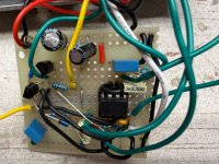
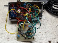
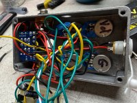
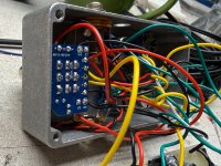
My first post. Hi everyone I need help. Building from a Zendrive/Hermida schematic. It passed all continuity testing. All voltages where good. Pin one, 4.78 V pin 2 4.78 V pin 3 4.60 V pin 4 0 V and pin 5 4.78 V and pin 6 4.78 V pin 7 4.78 V pin 8 9.51 V. I plug it in and all I get is a pedal I can turn the volume up or down from 0 to a normal loudness nothing strong. No distortion. No changes when I turn the gain,tone or voice knobs. I've looked at it under a microscope for solder bridging and everything looks good . Changes I made are using A pots instead of B pots and a 10k pot instead of a 50k pot for the Tone. Diodes I'm using Bat 41 and 1N4148. 2N7000 mosfets. And a TL072 IC with a socket. STUMPED
 
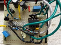
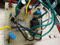
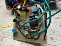
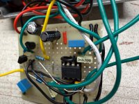
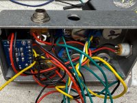
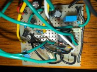
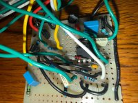
This is my pedal
 

Attachments

  • IMG_1220.jpeg
    IMG_1220.jpeg
    729.7 KB · Views: 14
  • IMG_1221.jpeg
    IMG_1221.jpeg
    822.3 KB · Views: 13
  • IMG_1222.jpeg
    IMG_1222.jpeg
    733.9 KB · Views: 11
  • IMG_1223.jpeg
    IMG_1223.jpeg
    668.4 KB · Views: 10
  • IMG_1224.jpeg
    IMG_1224.jpeg
    744.2 KB · Views: 11
  • IMG_1225.jpeg
    IMG_1225.jpeg
    1.1 MB · Views: 12
  • IMG_1226.jpeg
    IMG_1226.jpeg
    865.4 KB · Views: 11
  • IMG_1227.jpeg
    IMG_1227.jpeg
    869.8 KB · Views: 12
  • IMG_1228.jpeg
    IMG_1228.jpeg
    988.9 KB · Views: 14
Honestly I think that’s gonna be hard for any of us to trace what’s going on in the build.

Based on the Gain and Voice not working, I’d say check for the resistance between IC pin 1 and 2. (Should go from about 1k to 500k as the gain pot sweeps. Not sure why the Tone isn’t working if that was the problem.

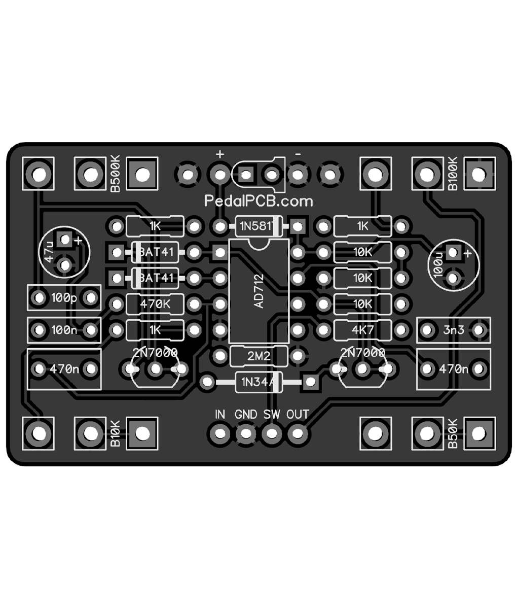
I’d agree the best bet is to build a pcb, or follow a layout like from tagboardeffects so that it’s easier to follow how its supposed to be wired.
 
I'll agree this is going to be difficult for us to help you debug, but if there's going to be any chance of it we'll need to see whatever layout you were following, be it one you found online or one you drew yourself, and we'll also need to see the solder side of the board.

All that said, there's absolutely no way we'll be able to tell what's going on with the offboard wiring, so if the problem is in there somewhere, we'll never be able to find it from behind a monitor.
 
Yeah dirtboxlayouts, tagboardeffects, etc vero images are very helpful for circuits not offered on ppcb or other vendors (or perhaps preferred for very simple or highly modded circuits). Buying a PCB when available just saves a huge amount of time and headache, and it looks nicer in the end.
 
Yeah, I know everything looks pretty when you buy boards premade. But that’s not the route I wanted to take I wanna learn. I know it’s a mess guys. I’ve already had this thing tore apart four times put back together. I managed to build an audio probe and I definitely have distortion from the gain now on lug 1. and definitely getting signal from lug one and two of the voice. As far as the tone goes, not really getting any response out of that, out of any lug. So I’m getting signal. It’s just not coming through the output jack. I’ll keep plucking I’ll give you more updates. I’m bound and determined to figure this out. Thanks for the replies.
 
Yeah, I know everything looks pretty when you buy boards premade. But that’s not the route I wanted to take I wanna learn. I know it’s a mess guys. I’ve already had this thing tore apart four times put back together. I managed to build an audio probe and I definitely have distortion from the gain now on lug 1. and definitely getting signal from lug one and two of the voice. As far as the tone goes, not really getting any response out of that, out of any lug. So I’m getting signal. It’s just not coming through the output jack. I’ll keep plucking I’ll give you more updates. I’m bound and determined to figure this out. Thanks for the replies.
So with the audio probe are you getting signal at the tone pot? Just clarifying. If you dont but you have it at pin 1 that should be fairly easy to pin point. If you have signal coming out of the tone pot but its not effecting it i would look at the cap that follows it (sorry don’t remember ref des) verify ground continuity and continuity wity lug 3 and the pin of the ic that follows.

I did all strip board and breadboard builds for my few builds with largely the same thought process. And troubleshooting them did teach me a fair amount. As did troubleshooting pcb builds after. I switched to pcbs and never looked back. My unsolicited advice for learning would be experiment and learn on a breadboard, then put your mods onto a pcb thats available if its feasible, if not Learn kicad or diptrace and make your own if the mods are extensive. Tracing down oh crap I put the wire in the wrong hole mistakes on a perf/vero doesn’t teach a lot playing with circuit blocks on a breadboard does.

Some cool stuff with filters

 
Holy moly what a day. I got it guys. Yep you said it soldered the wires in the wrong hole. I had my voice and tone wires switched. Also had R/3 connected to C3 R/3 was supposed to be by itself in its own row. And Lug 3 of the voice connected to that row. And then I was still having very subtle tone control and what I was using was a 10K and it calls for a 50K So now I have all kinds of treble. Kind of reminds me of that song It's all about that bass. Anyways thanks for the thoughts and ideas and this will not be the last pedal I build. This is my 4th one now. I built the Klon, two super hard ons, one for me and one for my son. And this Zendrive. Oh and also built a Mojotone British 50 watt the 1978 JMP 2204. But ya this Zendrive sounds nice.
 
Back
Top