You are using an out of date browser. It may not display this or other websites correctly.
You should upgrade or use an alternative browser.
You should upgrade or use an alternative browser.
CONTEST What? Another Contest?
- Thread starter Chuck D. Bones
- Start date
CONTEST
jubal81
Well-known member
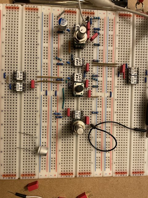
After going through a few ideas, I decided I wanted to keep my design as close to the original PCB as possible.
Hey, I always had big love for JFETs and Muffs - so, porque no los dos?
Wasn't sure what to expect, but this thing is Sofa King badass. The noise is also extraordinarily low - like eerily low, even at full gain.
Calling it the Fuzzduster for now. Will probably make a few tweaks, but it's already really close.
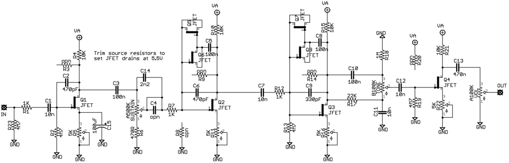
2SK880 JFETs with the source resistor trimmed to get 5.5V on the drain. Other 'high gain' JFETs should work just as well. The only deviations from the stock PCB are adding two extra caps - a source bypass on the input stage and a treble bleed on the gain pot.

Hey, I always had big love for JFETs and Muffs - so, porque no los dos?
Wasn't sure what to expect, but this thing is Sofa King badass. The noise is also extraordinarily low - like eerily low, even at full gain.
Calling it the Fuzzduster for now. Will probably make a few tweaks, but it's already really close.
2SK880 JFETs with the source resistor trimmed to get 5.5V on the drain. Other 'high gain' JFETs should work just as well. The only deviations from the stock PCB are adding two extra caps - a source bypass on the input stage and a treble bleed on the gain pot.
Last edited:
Blooze
Well-known member
Well after two evenings of jacking around on the breadboard I managed to make a distortion (modified zonk into a bosstone) that will compress so hard at full volume on the neck humbucker of my LP that it will almost fart completely out  On the other hand depending where it’s at in the room you can listen to several radio stations
  Back to the drawing board.
On the other hand depending where it’s at in the room you can listen to several radio stations Back to the drawing board.Chuck D. Bones
Circuit Wizard
Speed up the horizontal sweep and let's get a closer look at the HF noise. Is this that MOSFET circuit you showed me on Sat?Question..could that distortion in the CH1 peak be parasitic oscillation....or is it just likely plain noise from the breadboard?
Chuck D. Bones
Circuit Wizard
Interesting! Jubal81 loves him some JFETs! What resistances did you end up with on the trimmers?After going through a few ideas, I decided I wanted to keep my design as close to the original PCB as possible.
Hey, I always had big love for JFETs and Muffs - so, porque no los dos?
Wasn't sure what to expect, but this thing is Sofa King badass. The noise is also extraordinarily low - like eerily low, even at full gain.
Calling it the Fuzzduster for now. Will probably make a few tweaks, but it's already really close.
2SK880 JFETs with the source resistor trimmed to get 5.5V on the drain. Other 'high gain' JFETs should work just as well. The only deviations from the stock PCB are adding two extra caps - a source bypass on the input stage and a treble bleed on the gain pot.
jubal81
Well-known member
They're all between 1.8K and 2.4K.Interesting! Jubal81 loves him some JFETs! What resistances did you end up with on the trimmers?
BuddytheReow
Moderator
Chuck, was a little too eager (or perhaps lazy) to get this up before double checking everything. The resistor in question is 22k.Two more questions for BtR:
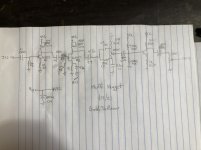
- What's the value of that mystery resistor connected to the high-side of the TONE pot?
- It's customary to put a capacitor between pin 2 of the TONE pot and the next transistor's bias network. Since your circuit doesn't have one, what happens to that transistor's bias when you turn the TONE pot?
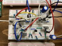
Secondly, you brought up something interesting regarding that missing coupling cap. At first I didn’t think it was necessary since there was a coupling cap before the tone control. I forgot that electricity goes BOTH ways. Turning the TONE pot does change the bias when looking at the transistors base voltage readings. Another little tidbit learned here. I have added the cap in the schematic and breadboard pic. See updated submission here.
Attachments
BuddytheReow
Moderator
For many of these circuits you can simply dial back your guitar's volume pot. I tend to dime MOST of my dirt pedals anyways, but there are a few exceptions such as a Rat.You're not a fan of Gain controls, are you?
fig
Village Idiot
That's sweet!Hey, I always had big love for JFETs and Muffs - so, porque no los dos?
There's your problem....try a breadboard!Back to the drawing board.

You just solved an issue on something else for me!I forgot that electricity goes BOTH ways.

Will do. No it's just a fetzer [but may end up with the MOSFET]. It seems I have a FETish as well.Speed up the horizontal sweep and let's get a closer look at the HF noise. Is this that MOSFET circuit you showed me on Sat?
btw, if anyone needs any odd bits for their entry, hit me up. I also have a few of the mini protoboards left if that is a barrier to someone's groovy entry. Free to good homes, and I'll throw in the hardware to build it. Solder it yourself though
jimilee
Well-known member
I could use some free time if you’ve got any laying around.That's sweet!
There's your problem....try a breadboard!
You just solved an issue on something else for me!
Will do. No it's just a fetzer [but may end up with the MOSFET]. It seems I have a FETish as well.
btw, if anyone needs any odd bits for their entry, hit me up. I also have a few of the mini protoboards left if that is a barrier to someone's groovy entry. Free to good homes, and I'll throw in the hardware to build it. Solder it yourself though
fig
Village Idiot
I spend most of that misnomer here too.I could use some free time if you’ve got any laying around.
")

BuddytheReow
Moderator
Only if @fig sends you one, LOL
Chuck D. Bones
Circuit Wizard

Chuck D. Bones
Circuit Wizard
BtR has got me all worked up now. I had to have a dose of fetzer.
A 2N5952 with a Vgs-off of -2.2V and Idss of 5.71mA.
The source is at 1.1VDC and the drain @ 4.5VDC.
")
The scope pic says the CH2 signal is 1.67Ap-p. How can that be right?
fig
Village Idiot
The scope pic says the CH2 signal is 1.67Ap-p. How can that be right?
What scope pic?

Ohhhh...I guess I build a mean fetzer?
Hang on, I'll re-create the "" scene of the crime. I was going to turn it on anyway to zoom in on channel one for someone (me).
Last edited:

Chuck D. Bones
Circuit Wizard
Zoom in more and measure the freq of the oscillation. Interesting that there are two regimes and the transition is pretty abrupt.
MOSFETs have a lotta bandwidth and make good RF oscillators, whether you're trying to build one or not. Does your circuit have a gate-stopper resistor? If not, try adding a 10K to 100K resistor in series with the gate. See if that kills the oscillations.
MOSFETs have a lotta bandwidth and make good RF oscillators, whether you're trying to build one or not. Does your circuit have a gate-stopper resistor? If not, try adding a 10K to 100K resistor in series with the gate. See if that kills the oscillations.