Nobelium - tube bass preamp project

@vigilante398

I thought I remembered seeing this info somewhere but I looked everywhere I could think of and didn’t see it. What frequency (roughly) does the treble control start affecting? Seems like somewhere down in the 4-5k range? Is there a spot I could try changing values to try getting that up a little higher? I find it’s just pulling a hair too much of the mids up with it. I thought if it was as easy as swapping out a resistor or two I might give it a whirl.

Thanks!
The Noble/Nobelium uses a Fender-style tonestack with a fixed mids response. It's a shelving filter with no fixed frequencies, and the controls are very interactive.

That being said, you could try increasing the value of the 270pF cap in the tonsetack to something like 470pF or 500pF, that should tame the highs a bit.
 
@vigilante398

I thought I remembered seeing this info somewhere but I looked everywhere I could think of and didn’t see it. What frequency (roughly) does the treble control start affecting? Seems like somewhere down in the 4-5k range?
That would be extraordinarily high as a starting point. By maybe an octave or two, at least. ;)
 
Check it in the TSC calculator first so you can see whats happening, remember to leave the Mid pot on 10 as the Nobelium uses R21 instead of a Mid pot.
Just click on "Edit" and change values and then click "Apply" and then you can slide the Bass and Treble pots to see what happens, you can also change the R21 resistance but keep the "Mid" pot slider on 10 since it is a fixed resistor.
Here is the link to the TSC already set for the Nobeliums tone stack: https://www.guitarscience.net/tsc/f...C3=100n&RB_pot=LogA&RM_pot=Linear&RT_pot=LogA
 
I just noticed that it looks like the 1/4" output seems wired in reverse, the signal is wired to the shield ring and the ground is wired to the tip on the socket.
If the 1/4" out works the socket must be insulated from the box by the powder coating only, it would be best if the wires were reversed to the correct position.
I must have looked at the picture lots of times and not noticed until now.
Cheers
Mick
You noticed right.
I already sell the nobelium to my friend and I noticed it while testing. It’s already changed.
 
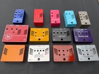
There are drill guides and art work for all the C2CE projects on the C2CE webpage, there is white artwork for dark boxes and black artwork for light boxes.
I get them made at Tayda since they can drill and apply the artwork to any box they sell.


Attachments

  • IMG_0093.JPG
    IMG_0093.JPG
    601.5 KB · Views: 31
  • 125B Boxes.JPG
    125B Boxes.JPG
    822.9 KB · Views: 26
There are drill guides and art work for all the C2CE projects on the C2CE webpage, there is white artwork for dark boxes and black artwork for light boxes.
I get them made at Tayda since they can drill and apply the artwork to any box they sell.


You’re the best. Thank you! Got it all boxed up but not getting any output 🤕 now begins the process of troubleshooting
 
I am getting a very high pitched squeal from mine. It’s fairly quiet but becomes noticeable when the preamp gets gained up. Does anyone else have this noise? Any ideas what could be causing it?

Thanks
 
You're missing the 6k8 and trimpot before you hit the transformer, but otherwise looks good. The 6k8 inline with the signal is in the original, the trimpot was my addition because I don't like the idea of a fixed level output on a preamp and have heard some people complain the original's output is too hot.

View attachment 65135
I have a few technical questions related to the circuit, I would like to address on this forum.

I have built my own replica of the Nobel, I used this circuit diagram, similar to Nobelium power supply circuit powered by 555 and Jensen output transformer. The preamp works well, but after playing through it for several days and comparing the sound (subjective) to reviews of Nobel and Nobelium on Youtube, I conclude that there are some sound differences (even though they seem minor). In my case, as well as in cases with Nobelium, the adjustment of Treble works in slightly different way: there is much more treble when cranking the level up, also it seem to affect higher range of treble which is less interesting for bass guitar, at least for me.

Another noticeable difference is slightly more compression and "omph" on the bottom end. One can say, the bass is a little more 3-dimensional, this is what I hear at least. Sounds like there is some slight phase shift on the bottom end.

It is interesting that the sonic performance of my preamp is nearly identical to Nobelium, which makes me think there might be some circuit differences between the actual Nobel and the circuit above. Another explanation could be the influence of component manufacturers, physical board arrangement or the effect of plate power supply - Noble is using linear rectifier while circuit above - PWM with simple filtering - one 10 uF cap. I would most likely believe the sound difference is due to either differences in the circuit or the PSU, which can affect the sound quite noticeably as well.

Has anyone had a possibility to verify the circuit and compare in to the actual Nobel? Especially the parts of the tone stack, plate voltages, cathode voltages?
Does anyone have access to detailed pictures of the boards of the Nobel?

Thanks!
 
Has anyone had a possibility to verify the circuit and compare in to the actual Nobel? Especially the parts of the tone stack, plate voltages, cathode voltages?
Does anyone have access to detailed pictures of the boards of the Nobel?

Thanks!
I mean I have obviously checked my circuit against the actual Noble, the only thing I'm missing is the B+ voltage, which I swear I wrote down somewhere but haven't been able to find since.

The power supply will account for a lot of differences, especially when it comes to feel, but I will also say it's impossible to compare a pedal in your hands to a pedal on your screen. If your benchmark is someone else's demo, you're never going to be satisfied. If you're trying to get a 100% accurate Noble, you're either going to have to buy an original or you're going to have to use components that are more accurate to the original, including the power transformer, which Jack gets custom made and is undoubtedly the most expensive part of the original units.

My goal with Nobelium as a project wasn't to create a 100% perfect accurate clone, my goal was to get you at least 90% of the way there for about 10% of the price of the original. I don't feel like Nobelium is taking sales away from Noble, because if you really want a Noble, you won't be happy with a Nobelium.
 
vigilante398, thank you for the answer. I think honestly you have definitely achieved your goal with 90%, great work!

I am an electronic enthusiast and my goal with my clone is to have fun with diy project, learn something new and experiment with the circuit. No commercial interest at all. I do not think the Noble circuit is the one I will end up with in the end, most likely it will be somewhat modified to my taste. For now I am trying to understand the circuit and the effect of the components on the sound.

I can play around with different B+ voltage levels as there is a possibility to adjust the voltage with R7/R8 ratio.

What I have done so far, instead of the 2,7 kOhm resistor in tone stack I installed a 2,4 kOhm resistor in series with a 2,2 kOhm pot, which gives a little room for adjusting the midrange. Boosting the midrange a bit to 3-4 kOhm brings some a little more life into the sound. Middle of the pot matches exactly the point of 2,7 kOhm.
 
I will be experimenting with the circuit to see what I can achieve with it. I can share my findings in this thread if it is welcome.

I was measuring around my replica with oscilloscope today. The B+ voltage after 10 uF + 0,47 uF is actually very good, very clean! I have PSU circuit which is very similar to Nobelium. However, the problem is in the EMF generated by the inductor, I use similar inductor to what is in Nobelium as well. The emitted EM noise from the inductor is picked up by the rest of the circuit causing ca 30 kHz switching noise. The circuit could also be oscillating a bit on high frequencies above audible. This could possibly explain the behavior of the Treb pot in my case. I was unlucky to prototype the PCB with the inductor located very close to signal chain.

I can think of a shield around the inductor could improve the situation significantly, and moving the inductor as much away as possible from signaling chain.

Regarding the B+ plate voltage, could it be that it is closer to 350V in the Noble? Looking at the tube specs, with ca 65 V plate voltage and current of under 1 mA per triode (which is the case with B+ of 250 V), they are in a "hungry" mode.
 
Hey, Nobelium Aficionados.

I just received my Nobelium kit from Musikding in Germany.
After many, many purchases from them I still don't know how Klaus does it at the prices he asks.

Every frickin' resistor has it's value written in immaculate handwriting on a tiny square of attached paper.
If there have been mods discussed online, he usually includes extra components to implement them for free.

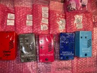
Included in the kit is.. absolutely everything. A nice set of JJ valves from Slovakia, the lovely Unagi* transformer and even the black Nobellium faceplate. I did not expect that, and even ordered one from C2C in advance.

As others have noted, Musikding isn't any more advanced than C2C in terms of machining slots into aluminium. The valve ventilation openings on the case are indeed a tidy series of round holes rather than slots. Also the ground lift switch has a hole drilled to allow it to be panel mounted.

All of this works fine but it means that that under the slotted faceplate there are ventilation holes rather than slots. Also the ground lift switch has a long bat, it sticks out maybe more than I would like.

All minor points. I may try my hand at joining up the ventilation holes into slots with a sharpie, Dremel tool and file.
For the ground lift switch, I'll enlarge and square the hole Klaus made and use a panel mounted slide switch.**
You could also use the switch as intended, mounted on the daughterboard, but you'd have to cut the slotted hole yourself.

With Musikding kits I used to substitute my own *****con electrolytic caps for the ones Klaus supplied. I hate replacing dried-out old electrolytics after some years, especially in valve amplifiers.
But I use the supplied ones now. I've beat them up, they seem pretty solid and temperature rated at 105C.

Thanks to vigilante and co (and Noble Co) for producing this original and variant design. Also for your open-handed knowledge sharing.

Pictures to come.


* (I keep wanting to say Ugali, the Swahilli word for cornmeal porridge, or Ugarte, Peter Lorre's character in Casablanca..)
** Why don't more pedal builders use slide switches? I love them, particularly for low profile applications like this.
 
Back
Top