Help measuring SMD JFETS

I don't know about you, but I want to invest as little as possible in SMD transistors and their accoutrements. I really dislike working with them. Maybe even loathe it. I found *one* SMD J201 out of a batch of 20 that I could pair at .93 IDSS with a .90 IDSS I had already soldered in my Deofol rework. Sure enough, it wasn't lining up to solder, I was moving it with needlenose tweezers, and it pinged right off the board, off my shirt, and into effing oblivion. So now I have to order another batch of 10 mmbfj201 and hope that one of them is >.90 IDSS
 
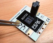
All this to avoid spending $40 on the jig from Peak heh

I have the jig from Peak, it's really a pain in the ass to use, especially if the part you're measuring has a little solder on the legs.

Mine collects dust while I solder them directly to a little SOT-23 adapter every time to measure.

I'm not being cheap, I hate the jig... I'd pay double for a working magnet solution. :ROFLMAO:
 
IDSS or Vp? 0.9mA for the MMBFJ201 seems to be really high value. -0.9V - ok (but in the higher range).
.090/.093, sorry. Yes, it's in the high range for J201, thus the frustration at losing it. Most are clocking between .040 and .08. Surprisingly, the Interfet through-hole are more consistent in their range in my measurement history.
 
I'm not a physicist, but I'd be curious what the relationship/curve of overall amount of Gauss to proximity is; i.e. the falloff of the field, or whether just using something weaker and putting it closer is less cumbersome.

Like, will something between a cheapo fridge decal magnet and rare earth be preferable? like a ceramic core. Bulk (height) of the buffer column is a consideration, yeah? I'd personally err on the side of just using a weaker magnet.

Tangentially related: I like my magnetic lug-nut, screw, bolt dish, but it attracts EVERYTHING on the underside, because that's where the magnet is: iron filings, everything. Putting a powerful magnet, spacing it out from the intended target area might could introduce a situation like that. Thoughts?
That just all makes my brain hurt.....
 
I'm not a physicist, but I'd be curious what the relationship/curve of overall amount of Gauss to proximity is; i.e. the falloff of the field, or whether just using something weaker and putting it closer is less cumbersome.

Like, will something between a cheapo fridge decal magnet and rare earth be preferable? like a ceramic core. Bulk (height) of the buffer column is a consideration, yeah? I'd personally err on the side of just using a weaker magnet.

Tangentially related: I like my magnetic lug-nut, screw, bolt dish, but it attracts EVERYTHING on the underside, because that's where the magnet is: iron filings, everything. Putting a powerful magnet, spacing it out from the intended target area might could introduce a situation like that. Thoughts?
All the better to use weak magnets, most likely, if magnets are the way. Currently exploring some ideas with my synth-building buddy who is deep into 3D printing.
 
Screenshot 2025-10-08 at 18.24.40.png

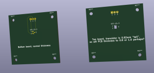
I've been thinking about this a bit before, my thoughts were mostly along the lines of taking KR Sounds' idea and make the hole smaller. (Robert posted link in this thread)

Bottom and top board screwed together, the top board has a small square hole, 2.40x2.92mm, where you put the transistor and I think you might need to put a little bit of pressure on the transistor for reliable contact with something relatively non-conductive

I don't know if this works well, and perhaps KR Sound's pcb with a bigger hole is actually better, just wanted to present my idea.
I haven't decided if I should try it or not.
 
I think the idea is that hole lets the transistor body through, but catches the legs and holds them against the pads.

Seems like it could be kind of a lengthy process to insert/remove the smd, and why is the clamping force so far away from the clamped object?
 
I was testing through a PCB I have with a few magnets from around the house, and the metal tweezers made it a challenge, as the field (even with a magnet just barely able to hold the JFET on the board) passed through the tweezers or whatever, made it "stick" and took me a hot minute to get it set on the pads.

the magnet (cheaper on off the back of a Buc'ee's magnet thing, 1.8mm thick) barely held it, but will hold it at 90*. No idea right now if there's enough of a good contact to take a measurement, but there's that.
 
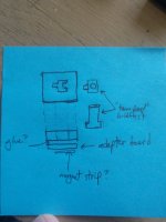
How hard would it be to 3D print a short column overtop of an adapter board with a keyhole in the middle the shape of a SMD transistor?

View attachment 104188
pretty easy to 3d print if you had dimensions or even better if you had a cad file... 3D printers are pretty accurate.. some times filament shrinkage is an issue with tolerance so if it's going to be something dimension specific I just start upscaling or downscaling by .5 to 1%
 
Back
Top