Building an Arachnid FV-1 board into a Boss enclosure (project)

CA138

Active member
Hi, I am planning a project involving trying to fit the Arachnid FV-1 PCB into a Boss enclosure. Not sure whether anyone has tried this yet and I couldn't find anything similar in the search.

1731928149937.png

Basically, I had a spare PH-3 enclosure laying around and haven't built an FV-1 pedal yet - I thought they might go well together.

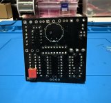
There appears to be enough clearance for compact jacks, 9mm pots and the board in the main compartment. I will need to work out how to make the square DC jack look pretty though...

1731928272998.png 1731928293748.png

Rate, Depth, Res controls will be CTRL 1, 2 and 3. The fourth control on the front panel will be the mini-rotary switch for the mode setting (flying leads all round of course). Volume can be an internal trimpot and for the mix control I plan to mount a 9mm pot on the side EXP hole.

Everything looks pretty straightforward, although I also had the idea of keeping the original Boss momentary switch and installing a relay bypass board in the battery compartment under the top cover. The clearance is 2x1 inches so it should fit. First time using a bypass board for me, but it looks as though this will work with the Boss switch - can anyone confirm?

1731928337348.png

Thanks for having a look - I'll post updates as I go if anyone is interested.
 
Test fitting looks good so far. Should be enough clearance for the main PCB when I get it. The offboard bypass board will be interesting.

A 16mm pot will fit nicely on the side in place of the EXP jack - although I will need to trim the legs back to rotate them into the recess and make sure heat-shrink is used to avoid shorting against the chassis. I am also confident I will get the mini rotary pot to fit the top panel.

1732266188182.png


Finally found a use for those white washers:

1732266222321.png
 
On the anniversary of this idea, I have finally moved to complete it.

Phase 1 is complete - Relay bypass mod set up, which fits nicely within the base of the main compartment and uses the original switch. This is a better option than my earlier plan to jam it into the battery compartment (which is now free for a small boost or fuzz circuit - or just spare picks or a battery..).

Now the easy part - populating the board. It fits the enclosure shell beautifully.

I left the worst for last - a tidy way to connect 20 flying leads to pots and the mode switch. The main volume pot was sacrificed to become an internal trimpot (hopefully the patches are consistent in volume so I can set and forget it).

Boss retrofit FV-1 - 2.jpg

Boss retrofit FV-1 - 1.jpg

Boss retrofit FV-1 - 3.jpg
 
Board is almost done, managed to squeeze film caps in and also keep the overall profile down to fit above the jacks. I had to stick one cap on the reverse side. Now to decide whether to use a TL074 or go with a OPA4134 (or OPA1644 with a SOIC adapter). Unsure how much it will matter on this circuit.

1 - Copy.JPEG
 

Attachments

  • IMG_7983 - Copy.JPEG
    IMG_7983 - Copy.JPEG
    259.2 KB · Views: 2
Last edited:
The main volume pot was sacrificed to become an internal trimpot (hopefully the patches are consistent in volume so I can set and forget it).
If necessary, you could drill a hole in the bottom and put some sort of a plug on it, so you could stick a screwdriver through to adjust it.

Still not ideal, of course, and hard to see a world where you need to tweak it enough to warrant a hole but not enough to put the pot on the side or something, buuut it is one possibility.

Great work all in all!
Thanks! I did consider the option of a small pilot hole for adjustments which I've done on other super compact builds, but thankfully the patches were all nicely unified in volume so that aspect has worked out perfectly.

Firstly, everything works ideally and it sounds great - especially the phaser patch which is on another dimension from the original in this pedal. The controls (1,2,3) work in very well with the Boss pot placement, and the old 'Stage' control is now the mix. I have the original Boss knobs and an extra for the side switch ready to go; however,...

*DISASTER*

There is some mild distortion in the effected signal. Bypassing and reducing the mix control are clean with no issue.

In itself, I would think perhaps a bad IC (I suppose not the OPAMP as it sounds fine bypassed and with mix turned down) BUT the L78L33 is scalding hot to the touch..

I haven't had time to start probing and diagnosing yet but I was careful in soldering and visual checks for possible shorts. On the face of it there may be a short somewhere, but I am yet to experience one in a build. I regret not taking the time to test the board before installation. I used to do this routinely but I guess I became overconfident due to never having any issues..

If anyone can give any clues due to experience with FV-1 builds as to the most likely issue/s I would appreciate it. I'm tempted to try swapping out the L78L33 but my gut tells me something else is causing it to overheat. I suspect overvoltage from another part of the circuit.

Otherwise, I'll start probing away when I next get time. Hopefully this doesn't end up back on the shelf for another year!
 
Your L78L33 regulator is installed backwards.
Thankyou Robert! I can't express how embarrassed I am at this.. Definitely the biggest slip of my pedal building adventure so far. A perfect example of trying to do too much too fast in late night bursts and not taking the time to diagnose for basic errors.

What do you think the damage estimate would be? I ran it for no more than about 2-3 minutes to test all functions. Hopefully I haven't ruined the other components.

Will replace the regulator and report back!
 
What do you think the damage estimate would be? I ran it for no more than about 2-3 minutes to test all functions. Hopefully I haven't ruined the other components.

Hopefully everything will be fine when you install it correctly.

The EEPROM and/or FV-1 IC could (and would eventually) be damaged, but hopefully they'll be OK.
 
Hopefully everything will be fine when you install it correctly.

The EEPROM and/or FV-1 IC could (and would eventually) be damaged, but hopefully they'll be OK.
Thanks so much. I'll fix this over the weekend and confirm. Appreciate the support.
 
Back
Top