Grounding with 3PDT Order Switch

greypilgrim76

Active member
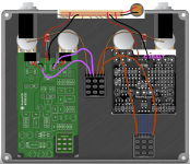
Quick question. I'm getting ready to start on my first two-pcb-in-one-enclosure project (combining a Blues Driver and Notaklon), and I'll be using the 3PDT Order Switch breakout board for the first time. The wiring diagram on the switch page is great for layout almost everything out:


1784765622078.png
But, the one thing I don't see is how to wire the grounds for each pcb. Should I just run the wires for each pcb to the input and output ground tabs as usual and just have two wires attached to each, or am I missing something really obvious here? (I always think I'm starting to understand electronics, and then I get stumped by something really simple like grounding...)

Anyway, thanks for any guidance!
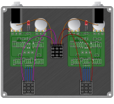
 
If you ground both PCBs to the power jack you should be fine. Just ground the phone jacks yo the nearest ground pad. It's basically like daisy chaining two pedals together, but all the wiring happens inside the enclosure.
 
Last edited:
Quick question. I'm getting ready to start on my first two-pcb-in-one-enclosure project (combining a Blues Driver and Notaklon), and I'll be using the 3PDT Order Switch breakout board for the first time. The wiring diagram on the switch page is great for layout almost everything out:


View attachment 121325
But, the one thing I don't see is how to wire the grounds for each pcb. Should I just run the wires for each pcb to the input and output ground tabs as usual and just have two wires attached to each, or am I missing something really obvious here? (I always think I'm starting to understand electronics, and then I get stumped by something really simple like grounding...)

Anyway, thanks for any guidance!

There are a number of different ways you could do it, but the way that @Aleph Null described is as good as any and will keep your wiring comparatively simple for a tidy build.
 
If you ground both PCBs to the power jack you should be fine. Just ground the phone jacks yo the nearest ground pad. It's basically like daisy chaining two pedals together, but all the wiring happens inside the enclosure.
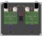
So if I'm reading this right, it would look something like this? (Or am I misunderstanding? Always a possibility!)
IMG_8788.jpeg
 
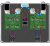
View attachment 121373
Your pic would probably work (I think they all go to a ground plane), but I think this is what @Aleph Null was describing.
Ah, I was this close. :)

So then, would I just leave the left ground tab on the right-side pcb and the right ground tab on the left-side pcb empty? (I'm guessing that those are both used on a normal single pcb setup to complete the ground, but here it's being completed elsewhere?)
 
All three of the ground pads at the top of the board are directly connected together so either way will work and are electrically identical.

(I'm guessing that those are both used on a normal single pcb setup to complete the ground, but here it's being completed elsewhere?)

Normally you have two 1/4" jacks and one DC jack per PCB. (Three ground connections total)

In this case you're omitting the output jack from the first pedal, and the input jack from the second pedal, so you have a pair of ground pads left over.
 
All three of the ground pads at the top of the board are directly connected together so either way will work and are electrically identical.


Normally you have two 1/4" jacks and one DC jack per PCB. (Three ground connections total)

In this case you're omitting the output jack from the first pedal, and the input jack from the second pedal, so you have a pair of ground pads left over.
See, this is the quality content I come here for. :) I feel like I'm starting to get a clear sense of how grounding works, but I didn't realize all of the grounds are connected. (*Reminds self for 100th time to always check schematic before asking questions*)
 
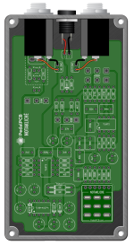
A follow-up question. I'd forgotten that the Notakliche has its own special breakout board and the in, out, and ground are routed to the top of the board:

1784824769890.png
In this configuration, I'm assuming that I just send one of the ground pads to the ground tab on the audio jack on that side of the pedal, per @genXslacker 's diagram above, but I'm not 100% clear regarding the connection between the "IN" and "OUT" pads at the top of the PCB and how they connect to "S2" and "R2" on the order switch breakout board. I'm thinking "IN" goes to "R2" and "OUT" goes to "R1," but I figure there's a 50/50 chance I've got that backwards.

Sorry for stacking questions on questions, but, to quote Henry Jones, Sr., "This is a new experience for me." :)
 
Back
Top