Audio Probe Build - Some Thoughts

BuddytheReow

Moderator
So, I’m thinking as my next project which will help future projects is to build an audio probe box.

It would be a 1590a with an input, output, and 9v jack. There would be a multimeter probe with a 100nf capacitor attached to the output jack, alligator clips for the power to the board, and a separate clip from the guitar input.

I’m thinking this could work. Now I have to figure out how to keep the cables nice when not using it. Maybe installing a handle or something to wrap the cables around?

Anyone build something like this before? Does this sound reasonable? I’m sick of my workbench looking like spaghetti with alligator clips everywhere. This build would greatly reduce those numbers, right?

Now the question is: how do I test it? I guess I would need an audio probe to make sure ?
 
A probe is always a good idea! I built one of the JMK test rig boards that includes an audio probe and a signal generator, for guitar free testing. Very useful (hopefully not too much of a faux pas to link to another PCB site given it's not something offered here).
 
My probe is made from a 15-20 foot guitar patch cable, I don’t use it very often but when I do I just take it off the wall and plug it into my looper and hang it back up after. I think having it so long makes me not leave it out haha.
 
I have scope probes and a couple of breakout boxes that contain two 1/4" phone jacks and a BNC jack for the scope probe. I plug one of those little battery-powered headphones amps into a 1/4" jack and probe around. Not just for troubleshooting, it's also good for tuning tone controls and the like. For input, I use a signal generator thru another breakout box that contains a volume knob, or a guitar.
 
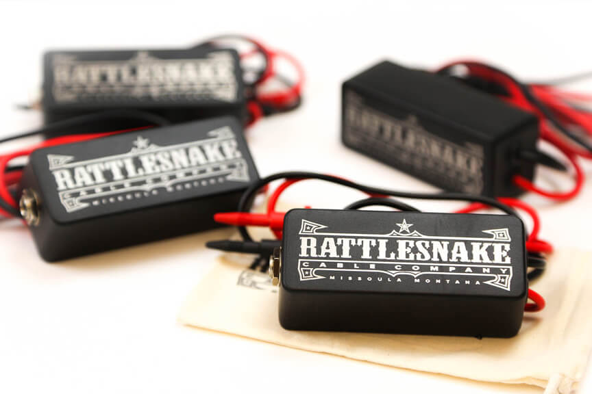
I bought one of these many many years ago when I was new to building; it was a game changer in diagnosing problems!


rattlesnake-cable-company-audio-probe.jpg

The build is very simple - two probe ends attached to the Tip and Ring of a 1/4" jack and secured internally to prevent pulling. Nothing more, nothing less!
 
So, I’m starting box everything up with the probe. I decided to use a binding post to simply plug in a multimeter lead for my test probe. Would I need to protect it from the enclosure somehow since the enclosure will be grounded? The post is merely a metal screw. Idk, electrical tape maybe?
 
I haven't made it yet, but I plan on building what's suggested at the bottom of this site: http://diy-fever.com/misc/audio-probe/

I bought some cheap DMM leads (waiting for these to arrive before building) and am going to be using one for the probe and an alligator clip for the ground. I like the idea of having a small probe that I can plug on to the end of a guitar cable.
 
@BuddytheReow How'd it come out?

I ended up throwing the probe together that I linked to the other day. I think it came out alright for my first butcher electronics job. Haven't had an opportunity to use it/test it out. I've gotta figure something out for the jack, though. I thought I had shrinkwrap large enough to fit over it, but I don't, so I'll probably just cut up a milk jug and see if I can't finagle something that way. Maybe I'll get one of those tiny little enclosures when I put my next order through, that might be kinda neat.

probe.jpg
 
Here it is. I finally finished it a few days ago. I used tagboard effects as a guide, but didn’t copy piece by piece. I chose alligator clips over the speaker terminal idea. I started getting confused how he wired the switches together, so I took out a notebook and figured it out myself which definitely helped from a learning perspective. Not the cleanest build underneath, but it serves its purpose. I am happy with this build and would recommend ANYONE who plans on building more than 2 pedals to build something like this. Definitely saves me the time of alligator clipping literally everything.


Attachments

  • 5A060ED0-80D2-4EBD-BFB3-1AE122D17F9B.jpeg
    5A060ED0-80D2-4EBD-BFB3-1AE122D17F9B.jpeg
    166.2 KB · Views: 37
  • 85FC10FA-794C-4B71-B641-AB4EBB3E2946.jpeg
    85FC10FA-794C-4B71-B641-AB4EBB3E2946.jpeg
    141.1 KB · Views: 31
  • 2674564B-40AA-48D7-9582-356E0F00A344.jpeg
    2674564B-40AA-48D7-9582-356E0F00A344.jpeg
    127.5 KB · Views: 34
  • 4E9F2B42-8738-41E5-AB02-943D84A46B31.jpeg
    4E9F2B42-8738-41E5-AB02-943D84A46B31.jpeg
    131.9 KB · Views: 37
Here it is. I finally finished it a few days ago. I used tagboard effects as a guide, but didn’t copy piece by piece. I chose alligator clips over the speaker terminal idea. I started getting confused how he wired the switches together, so I took out a notebook and figured it out myself which definitely helped from a learning perspective. Not the cleanest build underneath, but it serves its purpose. I am happy with this build and would recommend ANYONE who plans on building more than 2 pedals to build something like this. Definitely saves me the time of alligator clipping literally everything.


Looks great, man! Nice work.
 
Nice job! I recently built myself the JMK test rig, which has a built in probe and optional tone generator plus headphone output. It's been very helpful.
 
Back
Top