bassmancharlie
New member
Great to hear!I just went for it and it worked out ok. But feel free to post your pictures still as a resource to others who might need it!
For anyone else curious, here's a guide on how to socket the SMD J201s, using the SOT23 through hole adapters.
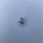
- Solder the SMD J201s to your SOT23 through hole adapter boards (not needed if you bought them pre-soldered)
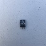
- Solder angled headers* to the adapter boards - the longer pins go through the adapter board, sticking out on the front side (J201 side, in this case)
- After the headers are soldered to the adapter boards, cut off the excess length of the soldered pins
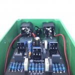
- Once that's good, solder to the main PCB (see last photo for orientation)
*angled header used was Tayda part A-199: https://www.taydaelectronics.com/40-pin-2-54-mm-angle-single-row-pin-header.html but any 2.54mm right angle single pin header will work


