Son of Ben / 2M Pot

almondcity

Well-known member
I cannot find any 2M PCB mount pots right now. I've bought a B1M pot for now with the thought of just installing it and missing the last half of that knob.

Is there a way of potentially inserting a 500K resistor in series with the pot in order to "shift" the range of my B1M pot towards where it should be? Like I would be OK if I can't turn my bass all the way to 0 or 10, but I would be OK with it going from 2.5 to 7.5. Forgive me if I'm talking nonsense

1625172231542.png
 
You can buy a comparable solder lug potentiometer, and transfer the resistive wafer to the housing of the PCB mount pot. It’s a bit of effort and it might take a few tries if you’ve never done it before, but after a while it becomes like second nature
 
Do you mean to just get both lugs in each hole on the PCB? Or solder one pair to the other and insert just one set?
 
Bringing this one back from the dead. Have had my version 2 board for a while but only now getting time to put it together over Christmas.

Soooo ... follow Feral Feline's suggestion, does that mean lug 1 of a dual B1M doesn't get connected?
 
For the SoB I just got a standard solder lug or vertical mount pcb pot and soldered hookup wire to it to extend to the mounts in the PCB. Solid core works great, but if braided just solder the entire extent of the wire. You've got three other pots that will secure the PCB in the enclosure.
 
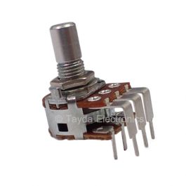
I just built my SoB last weekend using a PCB mount Dual 1MB, modified as the picture above.

I left the outer leads 1 and 2 alone. They go right into the PCB.
I clipped off the inner lead 1. It is not needed.
I bent the inner lead 2 and outer lead 3 toward each other, until they were flat and touching, then I soldered them together. Now they are joined and out of the way of the PCB.
I extended the inner lead 3 with a clipped diode leg to reach the PCB hole.
Then I soldered leads 1 and 2, and the extension of 3 to the PCB.

I should've taken a picture of it, hopefully this explanation made sense without the picture.
So basically like your diagram in post #8??
 
  • Like
Reactions: spi
For the SoB I just got a standard solder lug or vertical mount pcb pot and soldered hookup wire to it to extend to the mounts in the PCB. Solid core works great, but if braided just solder the entire extent of the wire. You've got three other pots that will secure the PCB in the enclosure.
Sorry to hop into this so late, but I'm collecting parts for doing this build and can only find the standard solder lug pots as well. Was it pretty easy to solder wire from the pot into the PCB mount holes? It looks like those openings are larger than the other through holes so I'm curious if you did anything differently when soldering the connections.
 
Bringing this one back from the dead. Have had my version 2 board for a while but only now getting time to put it together over Christmas.

Soooo ... follow Feral Feline's suggestion, does that mean lug 1 of a dual B1M doesn't get connected?


For some reason I missed this thread’s replies for a while…

I think it would be good to short the top gang’s lug 1 to top gang lug 2.

The lower gang’s lug 1 would go to the PCB’s pad-1 (be that in turn connected to ground or a resister etc depending on the circuit used.
 
  • Like
Reactions: fig
Bringing this thread up again since I have a short question:
I have a B2M at hand and the introduction says to bridge the two small extra solder pads between lugs 2 and 3 with solder. Since my lead-free solder is a bit difficult, I just bridged lugs 2 and 3 of the top row with a clipped diode wire - assuming this would have the same effect: is this correct?
That should work! If you had any 60/40 solder on hand it's also pretty easy to create a bridge between the two pads with just that.
 
Back
Top