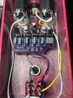
Moonn Night Destroyer - Low Volume?

Anyone out there put together a Night Destroyer by Moonn Electronics (https://moonnelectronics.bigcartel.com/product/night-destroyer) Got it as a "bonus" along with an order (Thanks, Nils!), and from the description its a clone of the Devi Ever Destructo Noctavia octave fuzz. Demo makes the original look pretty gnarly and noisy, so thought it'd be fun to assemble today.

Got everything together and plugged it in, and even when maxed I noticed the level is way below unity of my clean signal. Went through and checked for any bridges and reflowed all joins but still low output. Based on the schematic below, where would be a good place to start investigating? Or is it a case of changing a resistor value somewhere? I do think Q4 is incorrectly oriented on the PCB silkscreen, and rotating the 2N2222 by 180 degrees helped a bit, but still really quiet. Anyone else experience this issue? Thanks!
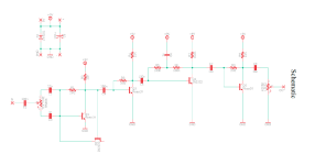
1718848875896.png
 
I've just made a thing that includes this pcb and I left Volume below noon which is a bit louder than the bypassed clean signal.
For Q4 I used a metal can 2N2222 acording to the pinout indications (EBC) on the pcb.
Q1-5 goes from right to left, I was a bit confused first by that order ....

Good luck it is noisy, gnarly and oscillating, but fun.
 
Thanks Fuzzonaut! I'll try moving some of the transistors around later this evening. Currently have metal can 2N2222A's in both Q2 and Q4. Did you sub in a PN2222A for Q2?

Side note: Is there a difference between 2N2222A vs 2N2222? I only have a bag of the former model. And the 2N2222A's I have measured slightly higher gain than the PN2222A's.

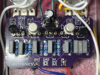
(And please excuse the sloppy wiring to the LED. It ain't pretty, but it works)

Night Destroyer (1).jpg
Night Destroyer (2).jpg
 
Swapped in two PN2222A's for the metal can 2N2222A's and the fuzz is now a bit more gnarly with more oscillation, but still no increase in volume, even at max level.

Maybe it's the MPSA18's causing the volume drop? Is there an HFE I should aim for with those? These are from Tayda, fwiw.
 
I first used the transistors the BoM called for (3x MPSA18 and 2x 2N2222), that was plenty loud and very wild. I then tried a 2N2222 in Q1 and it was still very loud. I think I left the 2N2222 in Q1 and called it a day.

The MPSA18's should have a hfe of around 600-700, I think. This circuit has so much gain, volume shouldn't be a concern.
Are all your (resistor/cap) values correct? If transistor swapping doesn't help, you might want to use an audio probe and follow the signal ....

(In your pic, Q2 and 4 are not oriented the same way, but that's on purpose, right?)
 
The MPSA18's I have are right around that hfe, so those seem to be good. Checked all cap and resistor values and those look correct. Guess it's time to get the audio probe. Thanks again for your help!
 
Yep, however from what I understand from the schematic, Q2 is wired like a diode with the emitter not connected to anything so it doesn't matter which way it's turned. Flipped it both ways and nothing is changed.

At this point I don't think the transistors are the issue behind the low volume. Will use the audio probe once I get a bit more time.
 
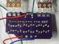
Got out the audio probe and when I touch the base of Q1, the volume jumps to what I would expect to be correct functionality. And when I press on the back of the PCB on the solder points for Q2 (circled), the volume jumps as well. So I'm guessing the issue is somewhere in that area. Any chance you see something amiss? Don't mind the bits of cotton bud I used when trying to clean off the flux. Night Destroyer (3).jpg
 
Try pressing on the tops of the transistors with something nonconductive. Like a pencil. Or chopstick(everyone needs a chopstick on their bench and in their toolbox. Luckily, they come in pairs!)
May have a bad connection in socket or between the socket pins and PCB.
Note, I'm reading it as volume increases in pedal output, not probe output.
 
Plugged everything in and pressed on the top of each transistor with a pencil, but unforutnately no change. Would it be best to just remove the sockets and solder in Q1-Q5 directly? I hesitate to pull out the sockets for fear of ruining a pad, but I'm a bit stumped here.
 
Picked this back up again after a bit of time away. Carefully removed all the sockets... no idea how I didn't lose a pad or two. Soldered in the transistors directly (swapped the PN2222a's for 2N2222a's from GPCB), but still the same low output. Cleaned up the joins and the input/output wiring and the 3pdt. Nothing.

Was about to throw in the towel, but started pushing a few things on the solder side while the effect was engaged and the output went way up to the expected level. Tracked down that I had inadvertently connected the leads (had yet to trim them off after soldering the transistors to the board) from Q5's collector and Q4's emitter. Soldered those together and we're in business. So, problem solved... i guess?
 
Back
Top