Simple Abider mods

HamishR

Well-known member
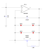
I bought a Dude when they first came out and liked it - except that perhaps it has a little bit more compression than I'd like. So I sold it to a friend. Then a few years later I see PedalPCB had a PCB for it called the Abider. So I built that, then remembered that I'd prefer a little less compression. So I built another one, only this time anywhere it has 2 x 1N4148 diodes as clippers I would add a pair of 1N4001 diodes just as the circuit does in the feedback loop of the last gain stage. So all in all there are three sets of clipping diodes; two in loops and one as hard clippers. In my new pedal all three sets of clipping diodes are a pair of 1N4001s in series with a pair of 1N4148s.

I love it! It has done exactly what I wanted. The compression is much lower and the feel is more natural - for me, anyway. Still a clear, creamy drive, just with a broader dynamic range now. I appreciate that not everyone will want less compression but I do, and this very simple mod has worked perfectly for me.
 
Yes. I have this thing about using 1N4148s with 1N4001s... I'm sure that if you just used 4 x 1N4148s it would sound the same. The main thing is that using a single pair of diodes is more compressed sounding than if you use two pairs.
 
I bought a Dude when they first came out and liked it - except that perhaps it has a little bit more compression than I'd like. So I sold it to a friend. Then a few years later I see PedalPCB had a PCB for it called the Abider. So I built that, then remembered that I'd prefer a little less compression. So I built another one, only this time anywhere it has 2 x 1N4148 diodes as clippers I would add a pair of 1N4001 diodes just as the circuit does in the feedback loop of the last gain stage. So all in all there are three sets of clipping diodes; two in loops and one as hard clippers. In my new pedal all three sets of clipping diodes are a pair of 1N4001s in series with a pair of 1N4148s.

I love it! It has done exactly what I wanted. The compression is much lower and the feel is more natural - for me, anyway. Still a clear, creamy drive, just with a broader dynamic range now. I appreciate that not everyone will want less compression but I do, and this very simple mod has worked perfectly for me.
So you just soldered the 4148/4001 in series and replaced the 4148's with this set? Turning the D1/D2 & D3/D4 clipping circuits into the same as D5/6/7/8 arrangement?
 
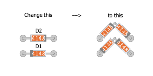
Where there is a pair of diodes shown on the board I used four. So i soldered in the diodes standing up (the diodes, not me) and connected them in pairs at the top. The board shows the outline of a diode - I install two in that space.
So you sit down when you solder? :D
Sometimes I'll sit but sometimes with my back problems it feels better to stand through a build.
 
Oh I always sit when soldering. Usually cross legged in a clearing in an ancient yew forest. Yew trees are legendary for how old they can grow, how their wood is toxic but can make the finest bows, and for usually having a handy 240V outlet at their base.
 
Just want to support this mod from @HamishR !

I wired the 2x 1n4148 pair locations on the PCB to a DPDT on/on switch and one side I used 2x 1n4148 symm for both locations. On the other side I uses the suggested 1n4148/1n4001 symm pairs for both locations on the PCB and that really opens the pedal up and increases the output as well. Great to have the more compressed option and the open sounding option to choose for different guitars for instance.
Do you mind showing a gut shot of how you did it? Or a drawing? :)
 
Do you mind showing a gut shot of how you did it? Or a drawing? :)

This post might help you out.

It's a 3-position diagram, on-off-on with LEDs in the middle, but you could leave out the LEDs for a diode-lift OR
use a 2-position on-on and skip the middle position altogether.
 
Just want to support this mod from @HamishR !

I wired the 2x 1n4148 pair locations on the PCB to a DPDT on/on switch and one side I used 2x 1n4148 symm for both locations. On the other side I uses the suggested 1n4148/1n4001 symm pairs for both locations on the PCB and that really opens the pedal up and increases the output as well. Great to have the more compressed option and the open sounding option to choose for different guitars for instance.
Hi Harmaes!

I want to try what you did but I'm confused about how it was implemented. Since there are 2 pairs at D1/D2 and D3/D4, did you need to wire them with 2 switches? If it was just one switch, how were you able to implement it? May I see a photo?

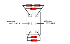
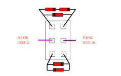
What I'm thinking is something like this

1723402392933.png

The top diodes would have the combo of 4148/4001 instead of just the asymmetrical one posted, and the bottom would have the normal symmetrical 4148s.
D1 through holes will be bridged, and then the purple and dark purple in the middle of the illustration will be wired to D2 through holes.

So I'd have to make two of these switches for D1/D2 + D3/D4?


Thank you!
 
Last edited:
Hi Harmaes!

I want to try what you did but I'm confused about how it was implemented. Since there are 2 pairs at D1/D2 and D3/D4, did you need to wire them with 2 switches? If it was just one switch, how were you able to implement it? May I see a photo?

What I'm thinking is something like this

View attachment 79933

The top diodes would have the combo of 4148/4001 instead of just the asymmetrical one posted, and the bottom would have the normal symmetrical 4148s.
D1 through holes will be bridged, and then the purple and dark purple in the middle of the illustration will be wired to D2 through holes.

So I'd have to make two of these switches for D1/D2 + D3/D4?


Thank you!

Sorry, I'm sleep-posting again... I don't understand what you're doing/trying-to-do. Can you show it on the schematic like HamishR did?

When you say "D1 through holes will be bridged", do you mean you're going to jumper D1, or that you're going to have two diodes in series in D1's place, on a switch? No need to jumper.

Is the switch in your quoted post above for the hard-clipping option alone or are you trying to turn off the soft clipping-diodes in D1 when you switch on the hard-clipping diodes? The diagram you posted shows the purple wires going to VOL lugs 3 & 1... but that's not where the switched diodes are going, right?


So I'd have to make two of these switches for D1/D2 + D3/D4?
One switch for each diode location, yes, one for the diodes at IC1.1 (D1/D2) and another switch for the diodes-to-ground D3/D4, if you want independent control of each set of diodes.
OR
wire a 4PDT to switch everything in one go.

If you use on-on switches, you'll have two options for each set of diodes, but if you use
on-off-on switches you could have either no-diodes in the middle switch position
or solder in some LEDs — or anything that has a combined higher-voltage than the outer two options of the switch(es).

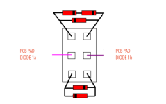
ANANSI 1.png

ANANSI 2.png

Think of a 4PDT as just two DPDTs that are sandwiched together with one toggle to operate both.
 
Back
Top