VA and VB in any given circuit

Cagno

New member
Hey!
Recently into the DIY pedal scene and have a question regarding voltages. In most schematic diagrams you see a VA and VB reference point.
How do you calculate or find these voltages if the schematic doesn't immediately specify what they are?
Are they universal voltages across any given schematic?


Thanks,
 
Without a specific example, you'll only get general answers. You'll have to look at the power section(s) to see what is happening to establish voltages at Va, Vb, etc. Are there voltage dividers involved? Charge pumps? More times than not, Vref is half the input voltage.

Head on over to the Test Kitchen for some general circuit knowledge. This may also help as well.
 
Thanks! I'll take a look at that post.

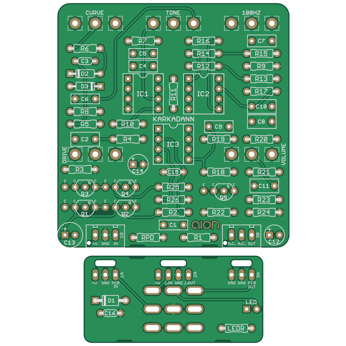
How about this given circuit? VA looks like 9v, but I'm not sure how to determine VB
Screen Shot 2024-07-18 at 1.10.20 PM.png
 
The voltage on pin 1 of IC3A will be equal to the voltage on pin 3 because it's a unity gain amplifier.

R25 and R26 form a voltage divider and we know VA is 9V, so:
VB = VA * (R26 / (R25 + R26)) (approximately 5.35V)
 
Wow, thank you for that information.
HYPOTHETICALLY if there was a capacitor in line with those voltage dividing resisters going to VB how would you calculate that?
 
C13, C14, and C15 are the filter caps for that circuit. They don't affect the DC voltage.

You wouldn't add any capacitors "in line" in that particular circuit since it's all DC, any series capacitors would block DC and wouldn't be useful there.
 
I'm guessing it was just a leftover unused stage... might as well go ahead and use it for something.

@Cagno What circuit is that? That Q1 - Q4 thing is weird.
 
I keep seeing the words "thermal runaway" in flashing red but this isn't parallel transistors in a power amp
 
Back
Top