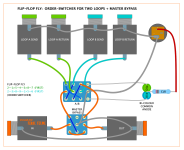
I've been building a lot of pedals lately and instead of boxing them all individually I've been using bigger enclosures and putting 3 in each. I wanted a way to switch the order since they are all hard wired inside and happened upon this old thread.
Anyway it got me thinking and I built this monster and it works, at least I get signal across all 6 positions and they sound different. Pardon my crayon drawing and my crappy wiring job but it was a real pain in the ass and I had to start over a couple times. It's also going to be a really tight fit. I'll probably buy another switch and do it from scratch now that I know it can be done and it is very cool but honestly I think just 2 toggle switches with one switching A and B and another that switches A+B and C would be way easier, just not as cool.
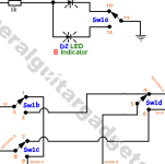
By special request, I was asked to add an LED to the momentary — though not necessary, it adds a bit of fun.
If you don't need/want an LED for the momentary, delete the above 3PDT-momentary's middle pole, and use a DPDT momentary instead.
I love ring modulators, noise makers, and anything that is particularly jarring or annoying sounding. So, this snippet of momentary switch-craftiness is great for just dropping in and out with freaky whacked out sounds.
But I have a question about this setup. As-is, when the latching switch is engaged (effect on) the momentary switch does nothing, yes? But, is it possible to wire this so that when the latching switch is engaged the momentary switch momentarily bypasses the effect? I gave up trying to figure it out. Any ideas?
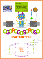
I built a stutter kill-switch that worked that way... when the signal was muted with the latching switch, the momentary activated the circuit and vice versa.
So I don't see why that wouldn't work with adding a PCB into the mix. I'll see if I can grab that info off my old computer's HD/and/or draw up a new diagram for you — but I won't have time to do it before next week.
“Tattarrattat”, goes the knock on your door, @moosapotamus! Eh, ça va, la vache?
Engage le jeu que je le gagne!
Pullup a chair, hear my tale of a car, a man, a maraca — NO! This is a tale of Signal-Langis.
Read on if you do not suffer from aibohphobia; no need to be evitative.
“Oho, no ho”, thought I as I couldn’t refer to the needed info on my old HD, a тот суп – пустота. Dammit I’m mad!
Evil is a deed, as I live…
Unlike a rotovator, I was unable to dig up the dumb mud on this idea.
“I’ll have to conjure up a switcheroo anew,” (‘cause that’s what I do).
“Tut-Tut” me-thinkered to myself, “Draw, O coward! I only but need to utter the magic words:
ALA KAZZAM AZZAKALA!”
Once stuttered forth, it was as though given a vorpal Xenex to wield against my manxome foe of fading memory, I slashed through the brainy cobwebs, and took on the mantle of Reifier.
Far from Deified, certainly not a member of the Igigi,
I am however a reviver — So revive this reversible-switch concept I shall, because… are we not drawn onward, no? In union, drawn onward to new era?
to reiterate, tare, tie, rot…
Are we not drawn onward, we few, drawn onward to new era?
I’ll eke it out from memory. Neither borrow or rob. Beats sitting on my thumb spinning like a rotator.
It’s my civic duty to dredge the depths of brain-fog and deliver, that’s my tenet.
Bear with me for a minim... while I may be Dr Awkward, I assure you everything’s on the level.
Nothing’s been deleveled.
Is it a one-trick pony? No, it is open on one position, though.
Never even…
Did it fail its goal? No, it can, as it is, (it is a war) raw as it is, it is an action. No lemon, no melon, no melon no lemon.
Works only one way? No, it is opposition. Never odd or even.
Was it difficult? Not a ton. Might now be my Switchery-Accomplishment top spot.
BRB
Huh? Where was I? Oh yes…
Did I do it? Did I? I did! YAY!
Gotta blow my own horn — TOOT TOOT!
So have a peep, bub, let me know if you think I’m a kook or belong with senile felines; maybe you think it’s poop, Gnu dung, or a dud — or maybe you'll simply ponder it with “WOW!”.
I think it’s versatile, usable for any circuit from a simple FF to a butt tuba.
With this switcher, evade no tone, not one, Dave! ... eh, Charlie.
Nicely done! You certainly seem to like a good challenge. I, myself, gave up on it after quite some time (well, maybe a couple days). But I never could suss it out. Congrats, nice job, and thank you for figuring it out. Awesome diagram, too!
I hope your mom is doing well. I've dealt with my own heart disease for years. It really sucks. So my thoughts are with you.
I've had this exact concept burbling in my back brain for a couple years. Actually gave it a go a couple times, even consulted a couple pros who deal in custom switchery. And here you've got it all laid out, color-coded with accompanying literary flair. High gratitude from me. I will be trying this out as soon as I can muster. I might even have the momentary four way around here...somewhere.
I got some 4PDT-Momentary switches from both a brick-and-mortar in Hong Kong, and from BLMS.
In fact, I've never seen them NOT on sale at BLMS, about 5.5 buckaroos — for just under $6, I should pick up a few more in case the discount stops, they get taken off sale, or aren't restocked, etc.
It can be a bit of a tongue-twister saying Ogopogogopogo. If you're familiar with the Ogopogo, just add "go pogo" to the end.
Or break it down further — Ogo Pogo Go Pogo, unless you want different emPHAsis on difFERent sylLABles, then maybe O go po gogo po go...
I'm Kelowna it here.
It can be a bit of a tongue-twister saying Ogopogogopogo. If you're familiar with the Ogopogo, just add "go pogo" to the end.
Or break it down further — Ogo Pogo Go Pogo, unless you want different emPHAsis on difFERent sylLABles, then maybe O go po gogo po go...
I'm Kelowna it here.
Haven't been able to squeeze in much soldering the last two weeks, even though I'm in the middle of a build.
So, with only a snippet of a moment here and there, I resort to toying around with DIYLC — the latest thing to grab my attention, again, is the humble order-switcher.
I was revisiting the GuitarPCB version (old build-doc, but the new one is basically the same), and it occurred to me that a person could maybe use it as a two-channel looper as well. So I started mapping out how to do that, and, well...
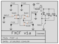
It seemed backwards, no matter which side of the PCB you solder the foot-switch onto. So I remapped it to my preference and suddenly I was easily able to work out the transformation of order-switcher to dual-loop switcher. That got me thinking further about how people learn differently or perceive things differently — for instance, "FX1I" and "FX1O" with "FX2I" and "FX20" seems convoluted to me: is the "I" in FX1I mean the signal coming IN to the switch and the "O" of FX1O the signal that needs to go from the order switcher to the FX1? No, in fact, it is the opposite, for example FX1I = SEND A to FX1's input.
Makes more sense to me to label them "Send A" and "Return A", etc. It's a minute difference in nomenclature, and you can still work it out, but nonetheless it's a stumbling block when looking at it from the perspective of the switch. I suppose if you're naturally inclined to look at it from the perspective of the effects-circuits, then the GPCB way makes more sense. Here's the GPCB schematic with its corresponding 4PDT's lug numbers added:
I was having trouble figuring out the "B" position where to re-route cables for using it as an A/B switch; I couldn't picture it in my mind and I kept following the "A" path midway through.
So I redrew it with the switch-gates flipped to the "B" position and that's when I realised how I think and use switch poles didn't jibe with how Tonman mapped it out.
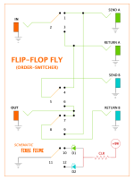
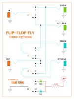
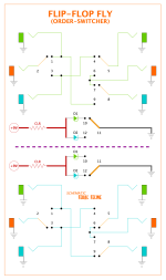
HERE's the schematic remapped to how I would hand-wire the switch when not using the GuitarPCB Easy Order PCB,
(PedalPCB's Order Switch is a 3PDT toggle so no LED capability, unless you jam the PCB on a 4PDT-stomper and hand-wire the LED/CLR/PWR) — To appease my brain, I've included both positions of the switch below:
My schematic above converted to corresponding diagram:
You can follow the little legend to the left of the 4PDT on the schematic.
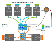
Now take the exact same circuit, no changes to it, but by plugging into/out-of different jacks we can turn it into an A/B loop-switcher;
Identical physical circuit, but I re-coloured some wiring and a couple jacks so you can better follow and differentiate the different paths for A and B:
Note that while the order-swapper—A/B-looper circuit is versatile, you might get pops when switching.
A dedicated A/B-Switcher with grounded inputs on the unused channel can be found here, earlier in this thread after jcpst clued me in on it. Good segue for the Tayda schematic he posted — maybe you look at the schematics I've posted and it's confusing, looks like it's all over the map — well it is. Here's the exact same circuit, perhaps for some, presented in a more logical way (Tayda-style):
Then with the switch flipped to follow the "B" path: [Hmmm it's JUST occurred to me that I should have a look at that grounded-A/B diagram in the thread and see if I can plug things in where they're not supposed to go to make an order-switcher out of it! ANSWER: NOPE!]
So, back to the circuit at hand — after I figured out which jack to plug in where, I realised there were a few more possibilities to be eked out of this simple order-switcher circuit, depending on what you plug into which jack... such as plug a guitar into the "Send B" in my schematic, and another guitar into "Return B" and you can switch between the two guitars, sending whichever one is active to your pedalboard/amp via the "OUT"
And then it hit me — this is basically the General Guitar Gadgets Translocator — a favourite of mine — which you can find the full project here, and the Translocator schematic PDF here. Well, duh, seems so obvious to me now. Who would've guessed the GPCB order switcher, an A/B-Loop Switcher and GGG Translocator were/are all the same durnblad thang?!
Ahh indeed, I just numbered up the GGG schematic ala how I would wire the switch and it matches my schematic perfectly.
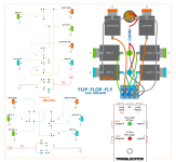
COMPARE the following snippet to the linked original GGG schematic and other schematics mentioned — all the jacks are labelled differently, but it's the same circuit at its core:
Highly recommend reading through GGG's "Translocator Operating Instructions.pdf", it'll show you how to use this thing to insert effects in and out of other loops, sections of pedal chain etc (application #5), and a bunch of other cool signal-pathway manipulations.
The one thing I don't recommend is using this circuit as an amp-switcher — too easy to get ground hums and it's not isolated so you could potentially damage your amps or worse?
Further to the above-mentioned GGG Translocator...
In the GGG documentation the LED-switching is done on SW1a. However, I've put the LED-switching on SW1d, and bumped the other poles over. If I'd kept to GGG's poles, then my SW1's lug numbers would've matched up as well.
Since I've already numbered everything and laid it all out, I'll ditch the GGG's switch-lug numbering and stick to my own numbering for that;
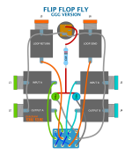
here's my version of the GGG layout:
Again, that perspective thing.
GGG has used the terms LOOP SEND (Jack 6) and LOOP RETURN (Jack 5) more or less as the main IN and OUT of the circuit, and the remaining jacks being used for loops A and B.
Myself and GPCB + others present the main IN and OUT of the circuit with what is GGG's Jack1 and Jack4, respectively, NOT Jacks 5&6.
Same exact circuit, yet many angles for looking at it, and a myriad of ways to label everything, too.
There are multiple ways to build it out. For instance, having A on one side and B on the other:
How 'bout...
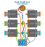
Clinging to the ancient side-jack paradigm and having ALL side-jacks with all the INs/RETURNs on one side and all the OUTs/SENDs on the other (Hey, maybe this all sidejacks version is what works best for routing on the pedalboard ):
Build it into a 1590BX2 and have ALL TOP JACKS !
(1032L?)
Try to cram it into a 1590A !
Use it to stick your Wah before or after dirt, use it to swap out two distortions, use it to pick your no... no. Not that. (Unless you have a really big nose).