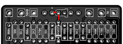
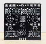
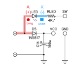
Looking at the Ungula schematic and PCB layout, I am confused by the square and circle pads of the LED.
As noted in this previous thread "The industry standard is square pad for the cathode of a diode".
When looking at the PCB layout it appears the (+) terminal is connected to the square pad and the positive of 1N5817 (D5) which should be the Anode of the LED (or the circle pad).
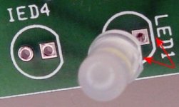
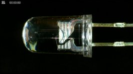
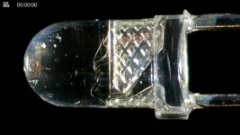
Can someone help me understand which way to place the LED? It appears the long leg of the LED (anode) needs to be placed in the square pad, however this is not the convention I would expect. Thanks!
Below is what I would expect:

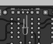
Below is what the PCB layout shows which shows the square pad connecting to the (+) which is not what I was expecting:

As noted in this previous thread "The industry standard is square pad for the cathode of a diode".
When looking at the PCB layout it appears the (+) terminal is connected to the square pad and the positive of 1N5817 (D5) which should be the Anode of the LED (or the circle pad).
Can someone help me understand which way to place the LED? It appears the long leg of the LED (anode) needs to be placed in the square pad, however this is not the convention I would expect. Thanks!
Below is what I would expect:
Below is what the PCB layout shows which shows the square pad connecting to the (+) which is not what I was expecting:
