LED Orientation

Munro306

New member
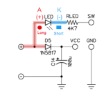
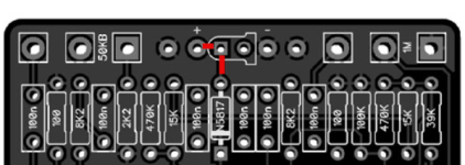
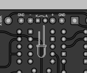
Looking at the Ungula schematic and PCB layout, I am confused by the square and circle pads of the LED.

As noted in this previous thread "The industry standard is square pad for the cathode of a diode".

When looking at the PCB layout it appears the (+) terminal is connected to the square pad and the positive of 1N5817 (D5) which should be the Anode of the LED (or the circle pad).

Can someone help me understand which way to place the LED? It appears the long leg of the LED (anode) needs to be placed in the square pad, however this is not the convention I would expect. Thanks!


Below is what I would expect:
1758122400830.png
Below is what the PCB layout shows which shows the square pad connecting to the (+) which is not what I was expecting:
1758122601811.png
 
There was a change in convention on some of the boards. Don't worry about the square vs round solder pad deal, just follow the letters A and K

 
Positive = long = anode (a)
negative = short = cathode (k)

If you remember that cats suck (cat-thode) and are lesser then dogs you wont ever forget.
Your welcome.


hiss-aristocrats.gif
 
There was a change in convention on some of the boards. Don't worry about the square vs round solder pad deal, just follow the letters A and K

But it’s not broken. We won’t know what to do! 🤣
 
I have strong preference for the round circle with a flat side, and I think it's the most friendly to beginners and intermediate but absent minded builders

Regarding Anode-cathode, there's also the confusion of anode being negative in batteries, but positive in capacitors and diodes. (Hope i didn't mess this up haha)

This isn't meant to be taken criticism or worse a demand for changes, pedalpcb boards are great as they are.

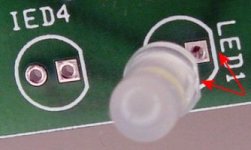
LED.jpg
 
Last edited:
I have strong preference for the round circle with a flat side, and I think it's the most friendly to beginners and intermediate but absent minded builders

Regarding Anode-cathode, there's also the confusion of anode being negative in batteries, but positive in capacitors and diodes. (Hope i didn't mess this up haha)

This isn't meant to be taken criticism or worse a demand for changes, pedalpcb boards are great as they are.

View attachment 103112
I did not realize that about batteries.
 
I have strong preference for the round circle with a flat side, and I think it's the most friendly to beginners and intermediate but absent minded builders

The absent-minded intermediate is exactly why I do all LEDs this way... beginners just follow the silkscreen and don't know about the convention, and advanced builders will take 10 seconds to do a continuity check if there is any uncertainty, but intermediates are much more likely to just insert the long leg into the square pad like an electrolytic without thinking about it.

For the first five years or so, all of my boards had square-anode LEDs. At some point I realized this was 'wrong' and so I updated my libraries to square-cathode. I immediately started getting 1-2 emails per week from people saying the LED didn't light up, and every time the solution was just to reverse it. The silkscreen never changed, only the pad shape, and the issue of the absent-minded intermediate became clear: they're the only ones who will ever do it backwards, and only with the square-cathode LED convention. So I changed it back to square-anode, and it's been several years since I've gotten an email about a backward LED. User-friendliness is my most important criteria, and if a convention causes more mistakes than it solves then the convention is not useful.

More recently I started marking "A" and "K" on the boards as well, which covers for the inconsistency between different designers. Between the silkscreen outline, A/K labels, and visual trace connectivity, there are enough ways to confirm the orientation that errors are almost nonexistent.

But, bottom line: always follow the silkscreen and you'll be OK. In CAD layout software, the silkscreen is downstream from everything else, so unless the schematic was drawn incorrectly, the silkscreen is going to be accurate.
 
I have strong preference for the round circle with a flat side, and I think it's the most friendly to beginners and intermediate but absent minded builders

I wouldn't be against it but (like all things) it isn't consistent.

Some (especially 3mm) LEDs don't have a flattened side for the silkscreen to serve as a point of reference...

Some don't have a longer lead, and some have a longer lead on the Cathode side.

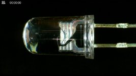
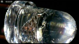
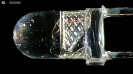
The only thing that I have found to be consistent, and how I identified the leads for years, is to look inside... the cathode lead connects to the "anvil" inside the plastic encapsulation. Yes, I had to Google that, I've always just called it "the bigger part".

The anvil/cathode lead is on top:
WIN_20250918_20_20_57_Pro.jpg
1758242485311.png
 
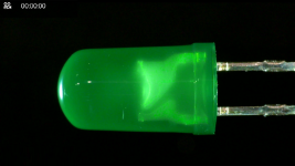
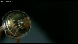
Slightly off topic, but I thought it'd be cool to take a peek inside these 3mm color cycling RGB LEDs while I was at it...

You can see the individual conductors and even the controller in the second photo.

WIN_20250918_20_29_02_Pro.jpg WIN_20250918_20_27_07_Pro.jpg
WIN_20250918_20_24_27_Pro.jpg
 
I put an LED in backwards tonight. Fortunately, I noticed before I soldered it in. I kept looking at it thinking something doesn’t look right.
 
Back
Top