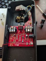
Vintage Cry-Baby

I'll wager that Robert would be willing to share the inductor footprint he uses on his Wah boards.

As for why I prefer tantalum in this application, I have stated in numerous threads that tantalum & film caps are highly transparent. The don't color the sound in any discernible way. Aluminum electros exhibit dielectric absorption that muddies the tone by smearing the transients. Their ESR varies with time & temperature. In the CryBaby circuit, that cap couples one end of the inductor to ground. The inductor and the 10nF cap that connects to the emitter of Q2 form the basis of the tuned circuit. They are the heart of the CryBaby. Any resistance, non-linearity, microphonics or time-domain artifacts (the afore-mentioned dielectric absorption) that sneak into that part of the circuit will alter the tone in a less than desirable way.
 
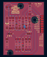
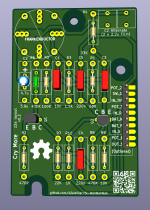
Not too hard to replicate since the layout was already done. It was mostly just annoying finding the honkin' big footprints to bury the normal-sized footprints in. It's a little bit different because the modern transistor pinouts (2N5088 or BC549B or whatever) are different so I swapped a couple of components around to reduce crossing. @Chuck D. Bones if you prefer the original transistor pinouts so it's really 1:1, LMK, it's an easy fix.

The NPTH for the mounting screws are best-guess using pixel measuring from available sources, I don't have a board in hand to bust out the calipers. I made them a little oversized (~4.5mm radius) so my guessing tolerance could be off a bit, but they look like M6-ish pan head screws so there's still lots of board to bite. There are zone fill keepouts so the screws don't bite through the soldermask and ground on the enclosure (ground loop prevention I guess, gotta emulate the ol' one layer boards, eh). But I guess if folks aren't too worried about that it'd probably be more durable to leave that coppered so the screws aren't just biting FR4.

I left myself a TODO to add some kind of DC jack header with power filtering. That usually involves losing ~2/3-3/4 of a volt, I don't know how much that'd change the character of this pedal (since I don't own one to test against and I'm toan deaf anyway), so I didn't do it right off. Also since the components are so honkin' big there actually isn't a lot of leftover room, though it's apparent from the gutshots that there's a bit of room to make the physical board larger if needed.

I used 0.1" headers for connections and extended out the pads to make hand-soldering a little easier. I also added individual landings for the pins that I saw that had multiple wires soldered to it, gawd, isn't soldering one wire to a post bad enough? I kept them at 0.1" spacing so you could install standard pin headers or a big JST XH connector -- but if people don't think that's worthwhile it'd probably be better to embiggen and enwiden the pad landings to make Soldering Wires To Things easier.

I need to figure out some kind of hydra inductor footprint but then I'm happy to share the gerbers.
(or the whole kicad project for that matter).
 

Attachments

  • Screenshot 2026-08-05 at 12.19.24 AM.png
    Screenshot 2026-08-05 at 12.19.24 AM.png
    284.8 KB · Views: 24
E-B-C transistor footprint is fine. BC549C/BC109C would be my standard for any CryBaby build. All of the usual suspects are viable as well. I'll get an accurate measurement on the board dimensions tomorrow. I'm out most of the day today.

Sounds good. I think I'm within +/-0.5mm for the NPTH mounts but would appreciate fully accurate measurements
to be sure, and let me shrink some of the holes/keepouts.

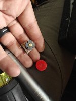
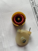
Also measure pin to pin X-Y on the inductor, too, if you get a chance - I can make a frankenfootprint that takes 2-pin
inductors but also has footings for the TDK 5103/dimes. (I had one created already before @Stickman393 kindly
provided theirs with some pixel-math estimates for the OG inductor layout)

He's basically looking for more sweep range and higher Q, both of which are easily attained with a few resistor changes.

Depending on which resistors, there's probably room even without removing the big footprints - if you LMK which
resistors you'd swap/tune, I can see if there's room for trimpots there. For some of the resistors, I might have to
juggle components around and/or remove the big footprint though.

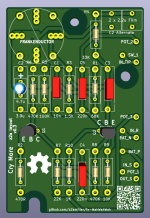
I was thinking I should also have room to parallel 2x2.2u wima film box caps in what's labeled as C2 on the board.
Less conflict-y. I see a place I could easily add them without having to move anything other than silkscreen.
(Upper right corner since that leg of L1 goes to top of R4 already).
 
I dropped the full KiCad project + Gerber .zip here (CERN-OSH-P licensed, no warrantee expressed or implied, etc):


I used Claude Code to help me with doing the photo measurements and stuff, and it helped make the
README file very flowery.

Happy to do fixups w/ trimpots, fix the mounts with more exact measurements, etc.
 
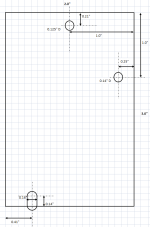
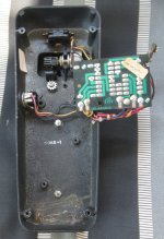
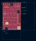
Here are the board dimensions that I measured on the unit pictured above. Top view.
All three holes should have a 3/8" dia keep out zone (no pads or traces) on both sides to clear the screws, washers and mounting bosses.
All three holes should NOT be thru plated.
The top center hole is not for mounting the board, it's a clearance hole for one of the screws that retain the treadle damper.
Board should be double-sided, thru plated (except as noted above) with ground pours on both sides.
External connections should be located approx as shown in the photo.

Grid is 0.1" x 0.1"

CryBaby board dimensions.png

Thomas 1977 Cry-Baby 03.jpg
 
Another note:

For those interested in doing one full up vintage-style with wire wrap posts, I found that the Vector T46-5-9 is fairly similar to what was originally used in these.

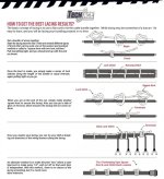
Also: the wire lacing techniques are fairly simple. All you need is a wax-impregnated flat ribbon thread and to follow the instructions on the photo:


1786301359300.jpeg

This was used quite often in old wiring harnesses, particularly in organs. No surprise there. Zip ties largely replaced this practice in modern electronics.
 
Thanks for the exact measurements. I've updated the board to the latest. My initial measurements were pretty close
(probably close enough to install). I did shrink the board to just a hair over 2 inches - it was ~2.25 before which gave
some more room for the wire harness connectors.

Still 0.1 pitch on the wire harness, but I could go with big PTHs for the offboard connections instead if you think that's more useful.
(which would allow the wire-wrap terminals).

(direct link to gerbers is here https://github.com/z2amiller/fx-WahWahWah/blob/main/GERBER-fx-WahWahWah.zip but
the whole kicad project is available in that repo)
 

Attachments

  • Screenshot 2026-08-09 at 3.54.43 PM.png
    Screenshot 2026-08-09 at 3.54.43 PM.png
    189.3 KB · Views: 11
  • Screenshot 2026-08-09 at 3.54.10 PM.png
    Screenshot 2026-08-09 at 3.54.10 PM.png
    277.4 KB · Views: 11
This was used quite often in old wiring harnesses, particularly in organs. No surprise there. Zip ties largely replaced this practice in modern electronics.
Love the lockstitch pr0n. Back in my ops monkey days, I worked in a datacenter where some old-guard telco folks had wired it, and all of the wiring was laced up with waxed cord like this, even the big one-inch-diameter DC power cables. ("Kansas City Stitch")
 
And here's a version with plain PTH for the offboard connections. (0.042" holes to match the Vector wirewrap posts).

The gerbers for this version are here. ("Download raw file")
The previous version w/ the 0.1" headers is here.
 

Attachments

  • Screenshot 2026-08-09 at 5.43.30 PM.png
    Screenshot 2026-08-09 at 5.43.30 PM.png
    225.6 KB · Views: 15
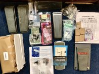
With my growing inventory of wah project parts, goona but those Gerbers to good use. Thanks!

Great! Let me know how they work out. I don't have any wah pedal stuff of my own so don't have any good
way to test. I'm happy to provide any bugfixes/improvements to the project if you find stuff that doesn't work
properly. Goofing around in KiCad is more engaging than turning off my brain watching Youtube.

(... I OWN a guitar, but can't play it. I just got into doing this stuff to hook up my shredding nephews)
 
Back
Top