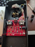
Vintage Cry-Baby

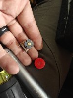
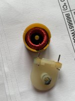
I'll wager that Robert would be willing to share the inductor footprint he uses on his Wah boards.

As for why I prefer tantalum in this application, I have stated in numerous threads that tantalum & film caps are highly transparent. The don't color the sound in any discernible way. Aluminum electros exhibit dielectric absorption that muddies the tone by smearing the transients. Their ESR varies with time & temperature. In the CryBaby circuit, that cap couples one end of the inductor to ground. The inductor and the 10nF cap that connects to the emitter of Q2 form the basis of the tuned circuit. They are the heart of the CryBaby. Any resistance, non-linearity, microphonics or time-domain artifacts (the afore-mentioned dielectric absorption) that sneak into that part of the circuit will alter the tone in a less than desirable way.
 
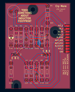
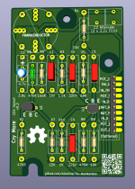
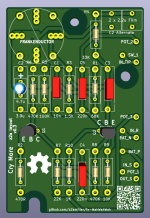
Not too hard to replicate since the layout was already done. It was mostly just annoying finding the honkin' big footprints to bury the normal-sized footprints in. It's a little bit different because the modern transistor pinouts (2N5088 or BC549B or whatever) are different so I swapped a couple of components around to reduce crossing. @Chuck D. Bones if you prefer the original transistor pinouts so it's really 1:1, LMK, it's an easy fix.

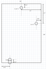
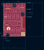
The NPTH for the mounting screws are best-guess using pixel measuring from available sources, I don't have a board in hand to bust out the calipers. I made them a little oversized (~4.5mm radius) so my guessing tolerance could be off a bit, but they look like M6-ish pan head screws so there's still lots of board to bite. There are zone fill keepouts so the screws don't bite through the soldermask and ground on the enclosure (ground loop prevention I guess, gotta emulate the ol' one layer boards, eh). But I guess if folks aren't too worried about that it'd probably be more durable to leave that coppered so the screws aren't just biting FR4.

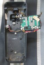
I left myself a TODO to add some kind of DC jack header with power filtering. That usually involves losing ~2/3-3/4 of a volt, I don't know how much that'd change the character of this pedal (since I don't own one to test against and I'm toan deaf anyway), so I didn't do it right off. Also since the components are so honkin' big there actually isn't a lot of leftover room, though it's apparent from the gutshots that there's a bit of room to make the physical board larger if needed.

I used 0.1" headers for connections and extended out the pads to make hand-soldering a little easier. I also added individual landings for the pins that I saw that had multiple wires soldered to it, gawd, isn't soldering one wire to a post bad enough? I kept them at 0.1" spacing so you could install standard pin headers or a big JST XH connector -- but if people don't think that's worthwhile it'd probably be better to embiggen and enwiden the pad landings to make Soldering Wires To Things easier.

I need to figure out some kind of hydra inductor footprint but then I'm happy to share the gerbers.
(or the whole kicad project for that matter).
 

Attachments

  • Screenshot 2026-08-05 at 12.19.24 AM.png
    Screenshot 2026-08-05 at 12.19.24 AM.png
    284.8 KB · Views: 9
E-B-C transistor footprint is fine. BC549C/BC109C would be my standard for any CryBaby build. All of the usual suspects are viable as well. I'll get an accurate measurement on the board dimensions tomorrow. I'm out most of the day today.
 
Back
Top